11-5-02
KEY: Inches[Millimeters] .XX ±.03 .XXX ±.010 [.X ±0.8 .XX ±0.25]
60 South Jefferson Road, Whippany, NJ 07981
Tel: 973-887-8100 ∑ Fax: 973-884-0445
email: sales@mcekdi-integrated.com
See us on the web @ www.mcekdi-integrated.com
COUPLERS, DIRECTIONAL SERIES CA-N
TYPE N 0.5-3 GHz
GENERAL INFORMATION
KDI/Triangle Miniature Stripline Couplers, Series CA-N, are available in
10 dB, 20 dB and 30 dB, coupling values. These units feature high direc-
tivity and low VSWR and are conservatively rated to ensure the most reli-
able service and performance under severe environmental conditions.
GENERAL SPECIFICATIONS
Frequency Range: 0.5 to 3 GHz
RF Impedance: 50 Ohms
RF Power: The peak and average power handling
capability of the couplers apply if the main
line is terminated in a 1.25 maximum
VSWR for the 10 dB couplers, and in a
1.75 maximum VSWR for the 20 and 30
dB couplers.
Operating Temperature: ≠55∞C to +85∞C
Connectors: N Female
Notes:
1. Rugged 4 hole connector construction insures mechanical superiority.
2. A 50 ohm termination is supplied on each unit delivered. Power rating
is 1.0 watts at +25∞C
Frequency Maximum Ins.
Frequency Coupling Flatness Minimum Maximum. Loss Above Maximum Maximum
Model Range (Note 1) (Note 1) Directivity Input/Output
Coupling Loss Peak Power Avg. Power Out-
No. GHz dB dB dB VSWR dB kW Watts line
CA-521-N .5-2.0 10 ±1.0 ±0.6 18 1.25 0.2 10 50 1
CA-522-N .5-2.0 20 ±1.2 ±0.7 18 1.25 0.2 10 50 1
CA-523-N .5-2.0 30 ±1.25 ±0.7 18 1.25 0.2 10 50 1
CA-631-N 1.5-3.0 10 ±1.0 ±0.6 18 1.25 0.2 7 50 2
CA-632-N 1.5-3.0 20 ±1.2 ±0.7 18 1.25 0.2 7 50 2
CA-633-N 1.5-3.0 30 ±1.25 ±0.7 18 1.25 0.2 7 50 2
ELECTRICAL PERFORMANCE
Notes:
1. Coupling includes Frequency Flatness. Coupling measurement is referenced to Input Port.
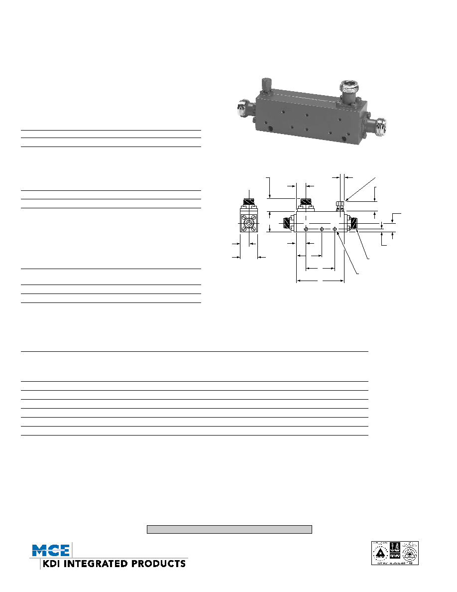
MECHANICAL OUTLINE
A B C D E
Outline in[mm] in[mm] in[mm] in[mm] in[mm]
1 3.50[88,9] 1.14[28,96] 0.50[12,7] 2.800[71,12] ≠
2 1.40[35,56] 1.14[28,96] -- -- 0.78[19,81]
,,,,,,
,,,,,,
,,,,,,
,,,,,,
,,,,,,
,,,,,,
,,,,,,
0.74[18,7] TYP.
0.50
[12,7]
1.00
[25,4]
0.156[3,96] DIA.THRU
MOUNTING HOLES
CPL
C
E
D
A
IN OUT
TERMINATION
0.20
[05,1]
0.50
[12,7]
0.50
[12,7]
0.55[14,0] MAX
0.13[03,3]
N FEMALE 3 PLCS.
B
SERIES
CAN-N
FIGURE 1
SERIES CA-N
OUTLINE