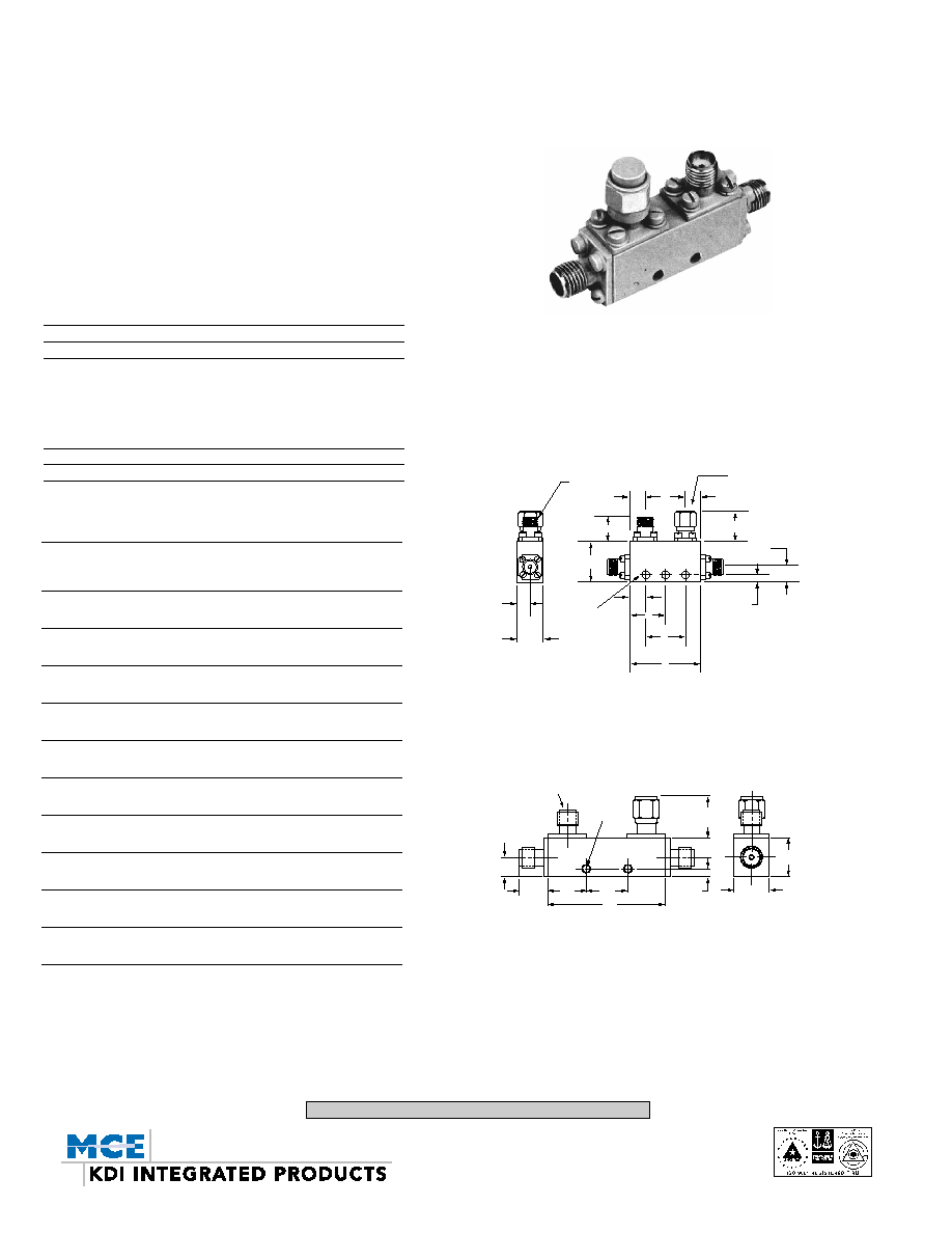
SUB-MINIATURE
COUPLERS, DIRECTIONAL SERIES CA, CL
SMA FEMALE 0.5-18 GHz
GENERAL INFORMATION
KDI/Triangle miniature stripline couplers, are available in 6 dB, 10 dB,
20 dB and 30dB, coupling values. These units feature high directivity
and low VSWR and are conservatively rated to ensure the most reli-
able service and performance under severe environmental conditions.
The directional couplers shown on this page are unequalled in terms
of size and performance. The volume of these couplers make them
ideally suited for applications involving high density packaging. As evi-
denced by the specifications, no compromise has been made with
electrical performance in order to achieve sub-miniaturization.
MECHANICAL OUTLINES
A B (Note 2) C D E
OUTLINE in in in in in
[mm] [mm] [mm] [mm] [mm]
1
3.10 0.50 0.80 1.50 ≠
[78,74] [12,7] [20,3] [38,1] ≠
2
3.40 0.50 0.95 1.50 ≠
[86,36] [12,7] [24,13] [38,1] ≠
3
2.50 0.50 0.60 1.30 ≠
[63,5] [12,7] [15,2] [33,02] ≠
4
1.80 0.55 0.43 0.94 ≠
[45,7] [13,97] [10,92] [23,88] ≠
5
1.40 0.50 0.50 0.40 ≠
[35,56] [12,7] [12,7] [10,2] ≠
6
1.00 0.50 ≠ ≠ 0.50
[25,4] [12,7] ≠ ≠ [12,7]
7
1.30 0.50 ≠ ≠ 0.65
[33,02] [12,7] [16,51]
8
0.90 0.50 ≠ ≠ 0.45
[22,86] [12,7] [11,4]
9
2.56 0.75 0.09 0.5 1.55
[65,02] [19,1] [2,29] [12,7] [39,37]
10
3.80 0.75 NA NA NA
[96,52] [19,1]
GENERAL SPECIFICATIONS
Frequency Range: 0.5 to 18.0 GHz
RF Impedance: 50 Ohms
RF Power: The peak and average power handling
capability of the couplers apply if the
main line is terminated in a 1.25 maxi-
mum VSWR for the 6 dB & 10 dB cou-
plers, and in a 1.75 maximum VSWR
for the 20 dB and 30 dB couplers.
Operating Temperature: ≠55∞C to +85∞C
Connectors: SMA female
SMA FEMALE TYP.
0.20[5,1]
0.38[9,7]
0.19[4.8]
0.38
[9,7]
0.093[2,36] DIA THRU
MOUNTING
HOLES
CPL
C
E
D
A
IN OUT
TERMINATION
0.20[5,1]
0.55[14,1] MAX
0.215[5,46]
0.075
[1,9]
B
TYPE "SMA" FEMALE
(3) PLS.
.62[15,8]
MAX.
C
.25[6,4]
TYP.
.38[9,65]
TYP.
D
±
.02[0,51]
E
±
.02[0,51]
A
±
.02[0,51]
.38
±
.003
[9,65
±
0,08]
B
±
.03
[0,76]
.104
±
.003 DIA.
[2,64
±
0,08]
(2) HOLES
Notes:
1. Rugged 4 hole connector construction insures mechanical superiority
2. For all 30 dB couplers B dimension is 0.55/[14.0]
3. 50 ohm termination is supplied on each unit delivered. Power rating is 1.0 watt at
+25∞C.
4. Coupling includes frequency flatness & coupling measurement in reference to
input port.
SERIES CL OUTLINES 9-10
SERIES CA OUTLINES 1-8
KEY: Inches[Millimeters] .XX ±.03 .XXX ±.010 [.X ±0.8 .XX ±0.25]
11-5-02
60 South Jefferson Road, Whippany, NJ 07981
Tel: 973-887-8100 ∑ Fax: 973-884-0445
email: sales@mcekdi-integrated.com
See us on the web @ www.mcekdi-integrated.com

Frequency Maximum Insertion
Frequency Coupling Flatness Minimum Maximum Loss Above Maximum Maximum
Model Range (Note 4) (Note 4) Directivity Input/Output Coupling Loss Peak Power Avg. Power
No. GHz dB dB dB VSWR dB kW Watts Outline
CA-516 .5-1.0 6 ± 1.0 ±0.6 18 1.20 0.15 3 50 1
CA-511 .5-1.0 10 ± 1.2 ±0.75 20 1.20 0.15 3 50 1
CA-512 .5-1.0 20 ± 1.2 ±0.75 20 1.20 0.15 3 50 1
CA-513 .5-1.0 30 ± 1.2 ±0.75 20 1.20 0.15 3 50 1
CA-526 .5-2.0 6 ± 1.0 ±0.6 18 1.20 0.2 3 50 2
CA-521 .5-2.0 10 ± 1.2 ±0.75 20 1.20 0.2 3 50 2
CA-522 .5-2.0 20 ± 1.2 ±0.75 20 1.20 0.2 3 50 2
CA-523 .5-2.0 30 ± 1.2 ±0.75 18 1.20 0.2 3 50 2
CL-7530-20 0.75-3.0 20 ± 1.0 ±0.75 20 1.30 0.2 3 100 9
CL-0833-10 .8-3.3 10 ± 1.25 ±0.75 20 1.25 0.2 3 100 9
CA-556 .75-1.5 6 ± 1.0 ±0.6 20 1.20 0.2 3 50 3
CA-551 .75-1.5 10 ± 1.2 ±0.75 20 1.20 0.2 3 50 3
CA-552 .75-1.5 20 ± 1.2 ±0.75 20 1.20 0.2 3 50 3
CA-553 .75-1.5 30 ± 1.2 ±0.75 20 1.20 0.2 3 50 3
CA-596 1.0-2.0 6 ± 1.0 ±0.6 20 1.20 0.2 3 50 4
CA-591 1.0-2.0 10 ± 1.2 ±0.75 20 1.20 0.2 3 50 4
CA-592 1.0-2.0 20 ± 1.2 ±0.75 20 1.20 0.2 3 50 4
CA-593 1.0-2.0 30 ± 1.2 ±0.75 20 1.20 0.2 3 50 4
CL-1040-20 1.0-4.0 20 ± 1.0 ±0.3 20 1.25 0.25 3 50 10
CA-636 1.5-3.0 6 ± 1.0 ±0.6 20 1.20 0.2 3 50 5
CA-631 1.5-3.0 10 ± 1.2 ±0.75 20 1.20 0.2 3 50 5
CA-632 1.5-3.0 20 ± 1.2 ±0.75 20 1.20 0.2 3 50 5
CA-633 1.5-3.0 30 ± 1.2 ±0.75 20 1.20 0.2 3 50 5
CA-676 2.0-4.0 6 ± 1.0 ±0.6 20 1.25 0.2 3 40 6
CA-671 2.0-4.0 10 ± 1.2 ±0.75 20 1.25 0.2 3 40 6
CA-672 2.0-4.0 20 ± 1.2 ±0.75 20 1.25 0.2 3 40 6
CA-673 2.0-4.0 30 ± 1.2 ±0.75 20 1.25 0.2 3 40 6
CA-696 2.0-8.0 6 ± 1.0 ±0.6 17 1.30 0.3 2 20 7
CA-691 2.0-8.0 10 ± 1.2 ±0.75 17 1.30 0.3 2 20 7
CA-692 2.0-8.0 20 ± 1.2 ±0.75 17 1.30 0.3 2 20 7
CA-693 2.0-8.0 30 ± 1.2 ±0.75 17 1.30 0.3 2 20 7
CA-716 2.6-5.2 6 ± 1.0 ±0.6 20 1.25 0.25 3 40 8
CA-711 2.6-5.2 10 ± 1.2 ±0.75 20 1.25 0.25 3 40 8
CA-712 2.5-5.2 20 ± 1.2 ±0.75 20 1.25 0.25 3 40 8
CA-713 2.6-5.2 30 ± 1.2 ±0.75 20 1.25 0.25 3 40 8
CA-776 6.0-18.0 6 ± 1.0 ±0.6 14 1.45 0.55 2 20 8
CA-771 6.0-18.0 10 ± 1.0 ±0.6 14 1.45 0.55 2 20 8
CA-772 6.0-18.0 20 ± 1.2 ±0.7 14 1.45 0.55 2 20 8
CA-773 6.0-18.0 30 ± 1.25 ±0.7 14 1.45 0.55 2 20 8
CA-756 4.0-8.0 6 ± 1.0 ±0.6 18 1.25 0.3 3 40 8
CA-751 4.0-8.0 10 ± 1.2 ±0.75 18 1.25 0.3 3 40 8
CA-752 4.0-8.0 20 ± 1.2 ±0.75 18 1.25 0.3 3 40 8
CA-753 4.0-8.0 30 ± 1.2 ±0.75 18 1.25 0.3 3 40 8
CA-796 7.0-12.4 6 ± 1.0 ±0.5 17 1.30 0.45 2 30 8
CA-791 7.0-12.4 10 ± 1.0 ±0.5 17 1.30 0.45 2 30 8
CA-792 7.0-12.4 20 ± 1.0 ±0.5 17 1.30 0.45 2 30 8
CA-793 7.0-12.4 30 ± 1.0 ±0.5 17 1.30 0.45 2 30 8
CA-836 8.0-16.0 6 ± 1.0 ±0.5 15 1.40 0.5 2 30 8
CA-831 8.0-16.0 10 ± 1.0 ±0.6 15 1.40 0.5 2 30 8
CA-832 8.0-16.0 20 ± 1.2 ±0.7 15 1.40 0.5 2 30 8
CA-833 8.0-16.0 30 ± 1.25 ±0.7 15 1.40 0.5 2 30 8
CA-876 8.0-18.0 6 ± 1.0 ±0.6 14 1.45 0.55 2 20 8
CA-871 8.0-18.0 10 ± 1.0 ±0.6 14 1.45 0.55 2 20 8
CA-872 8.0-18.0 20 ± 1.2 ±0.7 14 1.45 0.55 2 20 8
CA-873 8.0-18.0 30 ± 1.25 ±0.7 14 1.45 0.55 2 20 8
CA-916 12.4-18.0 6 ± 1.0 ±0.5 15 1.40 0.55 2 30 8
CA-911 12.4-18.0 10 ± 1.0 ±0.5 15 1.40 0.55 2 30 8
CA-912 12.4-18.0 20 ± 1.0 ±0.5 15 1.40 0.55 2 30 8
CA-913 12.4-18.0 30 ± 1.0 ±0.5 15 1.40 0.55 2 30 8
Notes:
1. Coupling includes Frequency Flatness. Coupling measurement is referenced to Input Port.
COUPLERS, DIRECTIONAL SERIES CA, CL
KEY: Inches[Millimeters] .XX ±.03 .XXX ±.010 [.X ±0.8 .XX ±0.25]
11-5-02
60 South Jefferson Road, Whippany, NJ 07981
Tel: 973-887-8100 ∑ Fax: 973-884-0445
email: sales@mcekdi-integrated.com
See us on the web @ www.mcekdi-integrated.com