
MODEL
CL-K59S
Dual Directional Coupler
TECHNICAL BULLETIN
Description
The specifications that are listed should be
considered as "representative" of a family of
directional couplers intended for high power, low
intermod performance, for cellular and PCS use.
The Model CL-K59S was designed for a custom
application in the transmitter path for base station
applications. The frequency range was limited
only by the particular system it was made for;
wider frequency bandwidth's and ranges are
available as may be needed for other
applications.
60 South Jefferson Road, Whippany, NJ 07981
TEL: 973-887-8100 * FAX: 973-884-0445 * web: www.kditriangle.com
email: sales@kditriangle.com
1
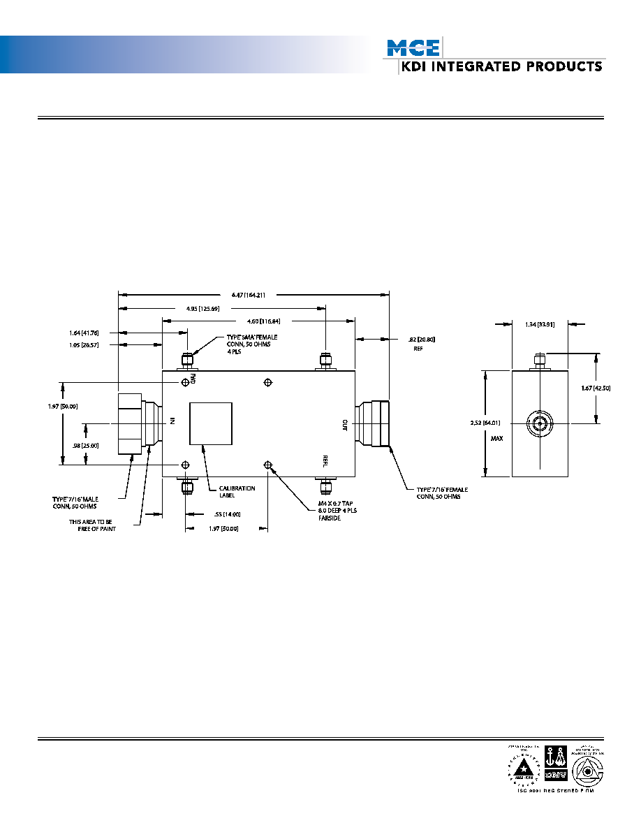
SPECIFICATIONS
Frequency:
860-870 MHz
Connectors:
7/16 male-fem
Coupling, forward and reverse:
30 dB
Tolerance:
+/ - 0.25 dB
Insertion Loss:
0.25 dB Max.
Directivity:
20 dB Min.
VSWR:
Main line:
1.06 Max.
Coupled ports
1.20 Max.
Maximum average input power:
400 Watts
IM performance:
-125 dBm in the band 898-925 MHz
Temperature Range:
-25 to 70 Degrees C
Environment:
Suitable for use in BTS applications.
The power input of each of two transmit signals applied to the input main line port to be 80
Watts ( average) in the frequency range 860-870 MHz.. The spectrum analyzer should be set
to Zero frequency span, 1 kHz resolution bandwidth, 1 kHz video bandwidth, and video
averaging of 100.
MODEL
CL-K59S
Dual Directional Coupler
TECHNICAL BULLETIN
60 South Jefferson Road, Whippany, NJ 07981
TEL: 973-887-8100 * FAX: 973-884-0445 * web: www.kditriangle.com
email: sales@kditriangle.com
2