 | –≠–ª–µ–∫—Ç—Ä–æ–Ω–Ω—ã–π –∫–æ–º–ø–æ–Ω–µ–Ω—Ç: KS8993M | –°–∫–∞—á–∞—Ç—å:  PDF PDF  ZIP ZIP |

Micrel-Kendin 486 Mercury Drive, Sunnyvale, CA 94085 USA (408)735-1118 http:www.Micrel.com
KS8993M 3-port Integrated Switch with PHY
F
EATURES
Proven 2
nd
generation of Integrated 3-port 10/100 Ethernet switch with 3 MACs and 2
PHYs (2+1)
Non-blocking architecture to assure fast packet delivery, with 1024 MAC address
table lookup and packet forwarding via store-and-forward architecture
MII registers can be accessed via MDIO bus or SPI bus
MII interfaces support both a MAC mode or PHY mode or 7-wire (SNI) mode
Automatic MDI/MDIX crossover for 100Base-TX and 10BaseT ports with disable and
enable option
Support 802.1Q VLAN up to 16 group
802.1p/q tag insertion or removal on a per port basis (egress)
QoS / CoS packets prioritization supports: per port, 802.1P and DiffServ based
Re-mapping of 802.1p priority field and VLAN ID field per port basis
LED Indicators for link, activity, full/half duplex and speed
Support Port Mirroring
Advanced Rate limiting
Management Information Base (MIB)
Power Dissipation: < 200mA including Physical transmit drivers
Plastic QFP 128 Package
1.8 volt for Vcc core and 3.3 volt for I/O
Confidential Information
Advanced information 1.00

KS8993M Integrated 3-port 10/100 Ethernet Switch
Micrel - Kendin Confidential Information Rev. 1.00 7/12/02
KS8993 Block Diagram
1K look-up
Engine
Queue
Mgmnt
Buffer
Mgmnt
Frame Buffers
F
I
F
O
,
F
l
ow C
o
nt
r
o
l
,
V
L
A
N
T
agg
i
ng ,
P
r
i
or
i
t
y
10/100
MAC 2
10/100
MAC 2
10/100
MAC 3
SNI
10/100
T/Tx 1
10/100
T/Tx 2
SPI
EEPROM
I/F
LED I/F
Auto
MDI/MDIX
Auto
MDI/MDIX
Control Reg I/F
K S 8993M
MIB
Counters
MII or SNI
LED1[3:1]
LED2[3:1]
Control
Registers
MDC & M DIO

KS8993M Integrated 3-port 10/100 Ethernet Switch
Micrel - Kendin Confidential Information Rev. 1.00 7/12/02
TABLE OF CONTENTS
KS8993 Block Diagram ...........................................................................2
1.0
Signal Description ............................................................................1
1.1 KS8993M Pin Diagram.................................................................................... 1
1.2 KS8993M Pin Description and I/O Assignment ............................................... 2
2.0
Advanced Functions ........................................................................9
2.1
Port Mirroring Support
............................................................................ 9
2.2
VLAN support
........................................................................................... 9
2.3 QoS Priority support ...................................................................................... 11
2.4
Rate Limit Support
................................................................................. 12
2.5 Static MAC address table.............................................................................. 12
2.6 VLAN table .................................................................................................... 13
2.7 Dynamic MAC address table......................................................................... 14
2.8 MIB (Management Information Base) counters............................................. 14
3.0
Package Outline and Dimensions ..................................................18
LIST OF TABLES AND FIGURES
Table 1 I/O Pin Out (by pin #)............................................................................... 2

KS8993M (3 Port 10/100 Integrated Switch with PHY)
Micrel - Kendin Confidential Information Rev. 1.00 7/12/02
1
1.0 Signal Description
1.1 KS8993M Pin Diagram
P
1LE
D
2
P
1LE
D
1
P
1LE
D
0
P
2LE
D
2
P
2LE
D
1
P
2LE
D
0
DG
ND
DV
CC
NC
NC
NC
NC
NC
NC
P1
SP
D
P1
PD
X
NC
P
W
RDN
AGN
D
AV
D
D
103
NC
NC
AD
V
F
C
P2
AN
E
N
P2
SP
D
P2
D
P
X
P2
F
F
C
NC
NC
DG
ND
DV
CC
NC
NC
NC
NC
P1
AN
E
N
P1
F
F
C
NC
1
2
3
4
5
6
7
8
9
10
11
12
13
14
15
16
17
18
19
20
21
22
23
24
25
26
27
28
29
30
31
32
33
34
35
36
37
38
AVDD
ISET
AGND
MUX1
MUX2
NC
RXP1
RXM1
AGND
TXP1
TXM1
VDDTX33
VDDRX33
RXP2
RXM2
AGND
TXP2
TXM2
AVDD
AGND
AGND
TEST1
TEST2
AGND
AVDD
PV
3
1
PS
0
PS
1
SP
I
S
_
N
SD
A
SC
L
SP
I
Q
MD
C
MD
I
O
SC
OL
S
M
RX
D1
S
M
RX
DV
SM
T
X
C
SM
T
X
D
0
SM
T
X
D
2
SM
T
X
E
N
SM
AC
BP
EN
RS
T
_
N
X2
PR
S
E
L
0
PR
S
E
L
1
DV
CC
DG
ND
SC
ON
F
0
SC
ON
F
1
S
CRS
S
M
RX
D0
S
M
RX
D2
S
M
RX
D3
SM
R
X
C
DV
CC
DG
ND
SM
T
X
E
R
SM
T
X
D
1
SM
T
X
D
3
LE
D
S
E
L
X1
10
2
10
1
10
0
99
98
97
96
95
94
93
92
91
90
89
88
87
86
85
84
83
82
81
80
79
78
77
76
75
74
73
72
71
70
69
68
67
66
65
SCANEN
PV23
TESTEN
P1_TAG RM
P2_TAG RM
P3_TAG RM
DVCC
DGND
P1_TAG INS
P2_TAG INS
P3_TAG INS
P1_PP
P2_PP
P3_PP
P1_TXQ2
P2_TXQ2
P3_TXQ2
P1_1PEN
P2_1PEN
P3_1PEN
PV13
PV12
DVCC
DGND
PV21
PV32
104
105
106
107
108
109
110
111
112
113
114
115
116
117
118
119
120
121
122
123
124
125
126
127
128
63
63
61
60
59
58
57
56
55
54
53
52
51
50
49
48
47
46
45
44
43
42
41
40
39
KS8993M
64
KENDIN
AGND
Top view

KS8993M (3 Port 10/100 Integrated Switch with PHY)
Micrel - Kendin Confidential Information Rev. 1.00 7/12/02
2
1.2 KS8993M Pin Description and I/O Assignment
Table 1 I/O Pin Out (by pin #)
Pin # Pin Name
Type
Description
1 P1LED2
I(pu)/O
2 P1LED1
I(pu)/O
3 P1LED0
I(pu)/O
Port 1 LED indicators, defined as below:
LEDSEL = 0
LEDSEL = 1
P1LED2
LINK/ACT
100LINK/ACT
P1LED1
FULLD/COL
10LINK/ACT
P1LED0
SPEED
FULLD
Note: LEDSEL is an external pin. Pin#
Note: During reset, these pins are inputs for internal
testing.
4 P2LED2
I(pu)/O
5 P2LED1
I(pu)/O
6 P2LED0
I(pu)/O
Port 2 LED indicators, defined as below:
LEDSEL = 0
LEDSEL = 1
P2LED2
LINK/ACT
100LINK/ACT
P2LED1
FULLD/COL
10LINK/ACT
P2LED0
SPEED
FULLD
Note: LEDSEL is an external pin. Pin#
Note: During reset, these pins are inputs for internal
testing and don't pull these pins down.
7 DGND
Gnd
Digital
Ground
8 DVCC
Pwr
Digital
Vcc
9 NC
Ipd NC
10 NC
Ipd NC
11 NC
Ipu NC
12
ADVFC
Ipu
1= advertise the switch's flow control capability via
auto-negotiation.
0 = will not advertise the switch's flow control
capability via auto-negotiation.
13
P2ANEN
Ipu
1 = enable Auto-negotiation on port 2.
0 = disable Auto-negotiation on port 2.
14
P2SPD
Ipd
1 = Force port 2 in 100BT if P2ANEN = 0.
0 = Force port 2 in 10BT if P2ANEN = 0.
15
P2DPX
Ipd
1 = port 2 default to full duplex mode if P2ANEN = 1
and auto negotiation fails. Force port 2 in Full duplex
mode if P2ANEN = 0.
0 = port 2 default to half duplex mode if P2ANEN = 1
and auto negotiation fails. Force port 2 in Half duplex
mode if P2ANEN = 0.
16
P2FFC
Ipd
1 = always enable (force) port 2 flow control feature

KS8993M (3 Port 10/100 Integrated Switch with PHY)
Micrel - Kendin Confidential Information Rev. 1.00 7/12/02
3
Pin # Pin Name
Type
Description
0 = flow control feature enable is determined by Auto
Negotiation result.
17 NC
Opu NC
18 NC
Ipd NC.
19 NC
Ipd NC
20 NC
Opd NC
21 DGND
Gnd Digital
Ground
22 DVCC
Pwr Digital
Vcc
23 NC
Ipd NC
24 NC
O NC
25 NC
O NC
26 NC
O
NC
27 NC
Ipd NC
28 NC
Ipd NC
29 NC
Ipd NC
30
P1ANEN
Ipu
1 = enable Auto-negotiation on port 1
0 = disable Auto-negotiation on port 1
31
P1SPD
Ipd
1 = Force port 1 in 100BT if P1ANEN = 0.
0 = Force port 1 in 10BT if P1ANEN = 0.
32
P1DPX
Ipd
1 = port 1 default to full duplex mode if P1ANEN = 1
and auto negotiation fails. Force port 1 in Full duplex
mode if P1ANEN = 0.
0 = port 1 default to half duplex mode if P1ANEN = 1
and auto negotiation fails. Force port 1 in Half duplex
mode if P1ANEN = 0.
33
P1FFC
Ipd
1 = always enable (force) port 1 flow control feature
0 = port 1 flow control feature enable is determined by
Auto Negotiation result.
34 NC
Ipd NC
35
NC
Ipd
NC
36
PWRDN
I
Chip power down input
37 AGND
GND
1.8v
gnd
38 AVDD
PWR
1.8v
vdd
39 AGND
GND
1.8v
gnd
40
MUX1
I
Factory test pin
41
MUX2
I
Factory test pin
42 AGND
GND
1.8v
gnd
43 AVDD
PWR
1.8v
vdd
44 NC
I
NC
45
RXP1
I/O
Physical receive or transmit signal + differential
46
RXM1
I/O
Physical receive or transmit signal - differential
47 AGND
GND
48
TXP1
I/O
Physical receive or transmit signal + differential
49
TXM1
I/O
Physical receive or transmit signal - differential
50 VDDTX33
PWR
3.3v
vdd
51 VDDRX33
PWR
3.3v
vdd
52
RXP2
I/O
Physical receive or transmit signal + differential
53
RXM2
O/O
Physical receive or transmit signal - differential
54 AGND
GND

KS8993M (3 Port 10/100 Integrated Switch with PHY)
Micrel - Kendin Confidential Information Rev. 1.00 7/12/02
4
Pin # Pin Name
Type
Description
55
TXP2
I/O
Physical receive or transmit signal + differential
56
TXM2
I/O
Physical receive or transmit signal - differential
57 AVDD
PWR
1.8v
gnd
58 AGND
GND
1.8v
vdd
59
TEST1
I
Factory test pin
60
TEST2
I
Factory test pin
61
ISET
O
Set physical transmit output current
62 AGND
GND
1.8v
gnd
63 AVDD
PWR
1.8v
vdd
64 AGND
GND
1.8v
vdd
65
X1
I
25 Mhz crystal connection
66
X2
O
25 Mhz crystal connection
67
RST_N
Ipu
Hardware reset pin
68
BPEN
Ipd
Half Duplex Backpressure Enable
69
SMAC
Ipd
Special Mac Mode. In this mode, the switch will do
faster backoffs than normal.
70
LEDSEL
Ipd
To select LED display mode.
LEDSEL = 0
LEDSEL = 1
PXLED2
LINK/ACT
100LINK/ACT
PXLED1
FULLD/COL
10LINK/ACT
PXLED0
SPEED
FULLD
71
SMTXEN
Ipd
Switch MII transmit enable
72
SMTXD3
Ipd
Switch MII transmit data bit 3
73
SMTXD2
Ipd
Switch MII transmit data bit 2
74
SMTXD1
Ipd
Switch MII transmit data bit 1
75
SMTXD0
Ipd
Switch MII transmit data bit 0
76
SMTXER
Ipd
Switch MII transmit error
77
SMTXC
Ipd/O
Switch MII transmit clock.
Output in PHY MII mode
Input in MAC MII mode
78
DGND
Gnd
Digital Ground
79 DVCC
Pwr Digital
Vcc
80 SMRXC
Ipd/O
Switch MII receive clock.
Output in PHY MII mode
Input in MAC MII mode
81
SMRXDV
O
Switch MII receive data valid
82
SMRXD3
Ipd / O
Switch MII receive data bit 3
Strap option: PD (default) = Disable Switch MII full-

KS8993M (3 Port 10/100 Integrated Switch with PHY)
Micrel - Kendin Confidential Information Rev. 1.00 7/12/02
5
Pin # Pin Name
Type
Description
duplex flow control; PU = Enable Switch MII full-
duplex flow control
83
SMRXD2
Ipd / O
Switch MII receive bit 2. Strap option: PD (default) =
Switch MII in half duplex mode; PU = Switch MII in
full-duplex mode.
84
SMRXD1
Ipd / O
Switch MII receive bit 1. Strap option: PD (default) =
Switch MII in 100Mbps mode; PU = Switch MII in
10Mbps mode
85
SMRXD0
Ipd / O
Switch MII receive bit 0; Strap option: see register
11[1].
86
SCOL
Ipd / O
Switch MII collision detect
87
SCRS
Ipd / O
Switch MII carrier sense
88 SCONF1
Ipd
89 SCONF0
Ipd
Switch MII interface configuration
(SCONF1, SCONF0)
Description
(0,0)
disable, output tri-stated
(0,1)
phy mode MII
(1,0)
mac mode MII
(1,1)
phy mode SNI
90 DGND
Gnd Digital
Ground
91
DVCC
Pwr
Digital Vcc
92 PRSEL1
Ipd
93 PRSEL0
Ipd
Priority Select. Select queue servicing if using split
queues. Use the table below to select desired
servicing. Note that this selection effects all split
transmit queue ports in the same way.
(PRSEL,PRSEL0)
Description
(0,0)
Transmit all high priority before
low prioirtu
(0,1)
Transmit high priority and low
priority at 10:1 ratio.
(1,0)
Transmit high priority and low
priority at 5:1 ratio.
(1,1)
Transmit high priority and low
priority at 2:1 ratio.
94
MDC
Ipu
MIIM interface clock input
95 MDIO
Ipu/O
MIIM interface data I/O
96 SPIQ
Opu Data
output
97
SCL
Ipu
Clock input
98
SDA
Ipu/O
Data I/O
99
SPIS_N
Ipu
Chip select

KS8993M (3 Port 10/100 Integrated Switch with PHY)
Micrel - Kendin Confidential Information Rev. 1.00 7/12/02
6
Pin # Pin Name
Type
Description
100 PS1
Ipd
101 PS0
Ipd
Configuration of interface signal for accessing
internal Registers
(PS1,PS0) = (0,0) : I2C EEPROM (master) mode (If EEPOM is not
detected, the power up default values in KS8993M internal registers
will be used)
Interface Signals
Type
Description
SPIQ
O
Unused. (tri-stated)
SCL
O
I2C clock
SDA
I/O
I2C data I/O
SPIS_N
Ipu
Unused.
(PS1,PS0) = (0,1) : I2C slave mode. Note the external master to
drive SCL. The default device 101-1111- R/W.
Interface Signals
Type
Description
SPIQ
O
Unused. (tri-stated)
SCL
I
I2C clock
SDA
I/O
I2C data I/O
SPIS_N
Ipu
Unused.
(PS1,PS0) = (1,0) : SPI slave mode
Interface Signals
Type
Description
SPIQ
O
SPI Data Out
SCL
I
SPI clock
SDA
I
SPI Data In
SPIS_N
Ipu
SPI chip select
102 PV31
Ipu
103 PV32
Ipu
Port 3 port based VLAN mask bits. Used to select
which ports may trasmit packets received on port 3.
PV31 = 1, port 1 may transmit packets received on port 3.
PV31 = 0, port 1 will not transmit any packets received on port 3.
PV32 = 1, port 2 may transmit packets received on port 3.
PV32 = 0, port 2 will not transmit any packets received on port 3.
104 PV21
Ipu
105 PV23
Ipu
Port 2 port based VLAN mask bits. Used to select
which ports may trasmit packets received on port 2.
PV21 = 1, port 1 may transmit packets received on port 2.
PV21 = 0, port 1 will not transmit any packets received on port 2.
PV23 = 1, port 3 may transmit packets received on port 2.
PV23 = 0, port 3 will not transmit any packets received on port 2.
106 DGND
Gnd Digital
Ground
107
DVCC
Pwr
Digital Vcc
108 PV12
Ipu
109 PV13
Ipu
Port 1 port based VLAN mask bits. Used to select
which ports may trasmit packets received on port 1.
PV12 = 1, port 2 may transmit packets received on port 1.
PV12 = 0, port 2 will not transmit any packets received on port 1.
PV13 = 1, port 3 may transmit packets received on port 1.
PV13 = 0, port 3 will not transmit any packets received on port 1.
110
P3_1PEN
Ipd
Enable port 3 ingress 802.1p priority classification.
The enable is from the receive perspective. If the
802.1p processing is disabled or there is no tag,

KS8993M (3 Port 10/100 Integrated Switch with PHY)
Micrel - Kendin Confidential Information Rev. 1.00 7/12/02
7
Pin # Pin Name
Type
Description
priority is determined by the P3_PP pin.
111
P2_1PEN
Ipd
Enable port 2 ingress 802.1p priority classification.
The enable is from the receive perspective. If the
802.1p processing is disabled or there is no tag,
priority is determined by the P2_PP pin.
112
P1_1PEN
Ipd
Enable port 1 ingress 802.1p priority classification.
The enable is from the receive perspective. If the
802.1p processing is disabled or there is no tag,
priority is determined by the P1_PP pin.
113
P3_TXQ2
Ipd
Selects transmit queue split on port 3. The split sets
up high and low priority queues. Note: packet priority
classification is done on ingress ports, via port
based,802.1p or TOS based scheme. The priority
enabled queueing on port 3 is set by P3_TXQ2
114
P2_TXQ2
Ipd
Selects transmit queue split on port 2. The split sets
up high and low priority queues. Note: packet priority
classification is done on ingress ports, via port
based,802.1p or TOS based scheme. The priority
enabled queueing on port 2 is set by P2_TXQ2
115
P1_TXQ2
Ipd
Selects transmit queue split on port 1. The split sets
up high and low priority queues. Note: packet priority
classification is done on ingress ports, via port
based,802.1p or TOS based scheme. The priority
enabled queueing on port 1 is set by P2_TXQ2
116
P3_PP
Ipd
Port 3 ingress default port priority. Note: 802.1p and
Diffserv, if applicable, will take precedence.
117
P2_PP
Ipd
Port 2 ingress default port priority. Note: 802.1p and
Diffserv, if applicable, will take precedence.
118
P1_PP
Ipd
Port 1 ingress default port priority. Note: 802.1p and
Diffserv, if applicable, will take precedence.
119
P3_TAGINS
Ipd
Enable tag insertion on port 3. All packets transmitted
from port 3 will have 802.1Q tag. Packets received
with tag will be sent out intact. Packets received
without tag will be tagged with ingress port's default
tag.
120
P2_TAGINS
Ipd
Enable tag insertion on port 2. All packets transmitted
from port 2 will have 802.1Q tag. Packets received
with tag will be sent out intact. Packets received
without tag will be tagged with ingress port's default
tag.
121
P1_TAGINS
Ipd
Enable tag insertion on port 1. All packets transmitted
from port 1 will have 802.1Q tag. Packets received
with tag will be sent out intact. Packets received
without tag will be tagged with ingress port's default
tag.
122 DGND
Gnd Digital
Ground
123
DVCC
Pwr
Digital VCC
124
P3_TAGRM
Ipd
Enable tag removal on port 3. All packets transmitted
from port 3 will not have 802.1Q tag. Packets
received with tag will be modified by removing 802.1Q

KS8993M (3 Port 10/100 Integrated Switch with PHY)
Micrel - Kendin Confidential Information Rev. 1.00 7/12/02
8
Pin # Pin Name
Type
Description
tag. Packets received without tag will be sent out
intact.
125
P2_TAGRM
Ipd
Enable tag removal on port 2. All packets transmitted
from port 2 will not have 802.1Q tag. Packets
received with tag will be modified by removing 802.1Q
tag. Packets received without tag will be sent out
intact.
126
P1_TAGRM
Ipd
Enable tag removal on port 1. All packets transmitted
from port 1 will not have 802.1Q tag. Packets
received with tag will be modified by removing 802.1Q
tag. Packets received without tag will be sent out
intact.
127
TESTEN
Ipd
Scan Test Enable
128
SCANEN
Ipd
Scan Test Scan Mux Enable
Note:
Pwr = power supply;
Gnd = ground;
I = input;
O = output;
I / O = bi-directional;
Ipu = input w/ internal pull-up;
Ipd = input w/ internal pull-down;
Ipd / O = input w/ internal pull-down during reset, output pin otherwise;
Ipu / O = input w/ internal pull-up during reset, output pin otherwise;
PU = strap pin pull-up;
PD = strap pull-down;
Otri = output tristated;
Opu = Output with internal pull-up
Opd = Output with internal pull-down

KS8993M (3 Port 10/100 Integrated Switch with PHY)
Micrel - Kendin Confidential Information Rev. 1.00 7/12/02
9
2.0 Advanced Functions
2.1 Port Mirroring Support
KS8993M supports "port mirror" comprehensively as:
(1), "receive only" mirror on a port. All the packets received on the port will be
mirrored on the sniffer port. For example, port 1 is programmed to be "rx sniff",
and port 2 is programmed to be the "sniffer port". A packet, received on port 1,
is destined to port 2 after the internal look up. The KS8993M will forward the
packet to both port 2 and port 3. KS8993M can optionally forward even "bad"
received packets to port 3.
(2), "transmit only" mirror on a port. All the packets transmitted on the port will be
mirrored on the sniffer port. For example, port 1 is programmed to be "tx sniff",
and port 3 is programmed to be the "sniffer port". A packet, received on any of
the ports, is destined to port 1 after the internal look up. The KS8993M will
forward the packet to both port 1 and port 3.
(3), "receive and transmit" mirror on two ports. All the packets received on port A
AND transmitted on port B will be mirrored on the sniffer port. To turn on the
"AND" feature, set register 5 bit 0 to 1. For example, port 1 is programmed to be
"rx sniff", port 2 is programmed to be "transmit sniff" and port 3 is programmed to
be the "sniffer port". A packet, received on port 1, is destined to port 2 after the
internal look up. The KS8993M will forward the packet to port 2 only, since it
does not meet the "AND" condition. A packet, received on port 1, is destined to
port 2 after the internal look up. The KS8993M will forward the packet to both
port 2 and port 3.
Multiple ports can be selected to be "rx sniffed" or "tx sniffed". And any port can
be selected to be the "sniffer port". All these per port features can be selected
through register 17.
2.2 VLAN support
KS8993M supports 16 active VLANs out of 4096 possible VLANs specified in
IEEE 802.1Q. KS8993M provides a 16-entry VLAN table, which converts VID
(12 bits) to FID (4bits) for address look up. If a non-tagged or null-VID-tagged
packet is received, the ingress port VID is used for look up. In the VLAN mode,
the look up process starts with VLAN table look up to determine whether the VID
is valid. If the VID is not valid, the packet will be dropped and its address will not
be learned. If the VID is valid, FID is retrieved for further look up. FID+DA is
used to determine the destination port. FID+SA is used for learning purposes.

KS8993M (3 Port 10/100 Integrated Switch with PHY)
Micrel - Kendin Confidential Information Rev. 1.00 7/12/02
10
FID+DA look up in the VLAN mode
DA found in
Static MAC
table
USE FID
flag?
FID match? DA+FID
found in
dynamic
MAC table
Action
No
Don't care
Don't care
No
Broadcast to the
membership ports
defined in the VLAN
table bit [20:16]
No
Don't care
Don't care
Yes
Send to the
destination port
defined in the dynamic
MAC table bit[54:52]
Yes
0
Don't care Don't care
Send to the
destination port(s)
defined in the static
MAC table bit[52:48]
Yes 1 No No Broadcast
to
the
membership ports
defined in the VLAN
table bit [20:16]
Yes 1
No Yes Send
to
the
destination port
defined in the dynamic
MAC table bit[54:52]
Yes 1
Yes Don't
care
Send
to
the
destination port(s)
defined in the static
MAC table bit[52:48]
FID+SA look up in the VLAN mode
SA+FID
found in
dynamic
MAC table
Action
No
The SA+FID will be learned into the dynamic table.
Yes
Time stamp will be updated.

KS8993M (3 Port 10/100 Integrated Switch with PHY)
Micrel - Kendin Confidential Information Rev. 1.00 7/12/02
11
Advanced VLAN features are also supported in KS8993M, such as "VLAN
ingress filtering" and "discard non PVID" defined in register 18 bit 6 and bit 5.
These features can be controlled on a port basis.
2.3 QoS Priority support
This feature provides QOS for applications such as VOIP, video conferencing,
and mission critical applications. The KS8993M per port transmit queue could be
split into two priority queues, high priority and low priority queues. The splitting
feature could be optionally per port enabled (using pin Px_TXQ2). If a port is
split, high priority packets will be put in the high priority queue. If a port's transmit
queue is not split, high priority and low priority packets will be treated equally.
There are four priority schemes (selected by pins PRSEL1 and PRSEL0): (1),
transmit high priority packets always before low priority packets, i.e. A low priority
packet could be transmitted only when the high priority queue is empty. (2), 10/1
ratio, transmit a low priority after every 10 high priority packets transmitted if both
queues are busy. (3), 5/1 ratio, (4) 2/1 ratio. Incoming packet priority could be
classified in two ways, port-based or 802.1p.
Port based priority: Each port could be individually specified as a high priority
receiving port (using pin Px_PP). All the packets received at the high priority
receiving port will be marked high priority and sent to the high priority transmit
queue if the corresponding queue is split.
802.1p based priority: 802.1p based priority could be enabled by pins
Px_1PEN. KS8993M will examine incoming packets to determine whether they
are tagged and retrieve the corresponding priority information. The priority field
in the VLAN tag is 3 bits wide and is compared against "priority base value
specified by register 2 bit 6-4. (the default value is 0x4). If a received packet has
an equal or larger priority value than the "priority base" value, the packet will be
put in the high priority transmit queue if the corresponding queue is split.
KS8993M can optionally remove or insert priority tagged frame's header (2 bytes
of tag protocol identifier 0x8100 and 2 bytes of tag control information). If a
transmitting port has its corresponding Px_TAGINS set (meaning tag insertion),
the transmitting logic will automatically insert tag with source port's default tag
value. For already tagged packets, KS8993M will pass the original packet
without changing its tag content. If a transmitting port has its corresponding
Px_TAGRM set (meaning tag removal), the transmitting logic will automatically
remove "802.1Q tag". For untagged packets, KS8993M will pass the original
packet without changing any content. Either tag insertion or removal will cause
CRC recalculation.

KS8993M (3 Port 10/100 Integrated Switch with PHY)
Micrel - Kendin Confidential Information Rev. 1.00 7/12/02
12
2.4 Rate Limit Support
KS8993M supports hardware rate limiting on "receive" and "transmit"
independently on a per port basis. It also supports rate limiting in a priority or
non-priority environment. The rate limit starts from 0 kbps and goes up to the line
rate in steps of 32 kbps. The KS8993M uses one second as an interval. At the
beginning of each interval, the counter is cleared to zero, and the rate limit
mechanism starts to count the number of bytes during this interval.
For receive, if the number of bytes exceeds the programmed limit, the switch will
stop receiving packets on the port until the "one second" interval expires. There
is an option provided for flow control to prevent packet loss. If the rate limit is
programmed greater than or equal to 128kbps and the byte counter is 8Kbytes
below the limit, the flow control will be triggered. If the rate limit is programmed
lower than 128kbps and the byte counter is 2Kbytes below the limit, the flow
control will be triggered.
For transmit, if the number of bytes exceeds the programmed limit, the switch will
stop transmitting packets on the port until the "one second" interval expires.
If priority is enabled, the KS8993M can support different rate controls for both
high priority and low priority packets. This can be programmed through registers.
2.5 Static MAC address table
KS8993M has a static and a dynamic address table. When a DA look up is
requested, both tables will be searched to make a packet forwarding decision.
When an SA look up is requested, only the dynamic table is searched for aging,
migration and learning purposes. The static DA look up result will have
precedence over the dynamic DA look up result. If there are DA matches in both
tables, the result from the static table will be used. The static table can only be
accessed and controlled by an external SPI master (usually a processor). The
entries in the static table will not be aged out by KS8993M. An external device
does all addition, modification and deletion.
Note: Register bit assignments are different for static MAC table reads and static
MAC table write as shown in the two tables below.

KS8993M (3 Port 10/100 Integrated Switch with PHY)
Micrel - Kendin Confidential Information Rev. 1.00 7/12/02
13
Format of static MAC table (8 entries)
Bit
Name
R/W
Description
Default
57-54
FID
W
Filter VLAN ID, representing one of the 16
active VLANs.
0000
53 Use
FID W
=1, use (FID+MAC) to look up in static table
=0, use MAC only to look up in static table
0
52 override W
=1, override port setting "transmit enable=0"
or "receive enable=0" setting.
=0, no override
0
51 valid
W
=1, this entry is valid, the look up result will
be used
=0, this entry is not valid
0
50-48 Forwarding
ports
W
The 3 bits control the forward ports, ex
001, forward to port 1
010, forward to port 2
100, forward to port 3
110, forward to port 2 and port 3
111, broadcasting (excluding the ingress
port)
00000
47-0 MAC
address
W
48 bit MAC address
0x0
2.6 VLAN table
VLAN table is used to do VLAN table look up. If 802.1Q VLAN mode is enabled (Register 5 bit 7
=1), this table will be used to retrieve VLAN information that the ingress packet is associated with.
The information includes FID(fiter ID), VID(VLAN ID), VLAN membership described below:
Format of static VLAN table (16 entries)
Bit
Name
R/W
Description
Default
19
Valid
R/W
=1, the entry is valid
=0, entry is invalid
1
18-16
Membership
R/W
Specify which ports are members of the
VLAN. If a DA look up fails (no match in
both static and dynamic tables), the packet
associated with this VLAN will be forwarded
to ports specified in this field. Eg. 11001
means port 5,4, and 1 are in this VLAN.
111
15-12
FID
R/W
Filter ID. KS8993M supports 16 active
VLANs represented by these four bit fields.
FID is the mapped ID. If 802.1Q VLAN is
enabled, the look up will be based on
FID+DA and FID+SA.
0
11-0
VID
R/W
IEEE 802.1Q 12 bit VLAN ID
1
If 802.1Q VLAN mode is enabled, KS8993M will assign a VID to every ingress packet. If the
packet is untagged or tagged with a null VID, the packet is assigned with the default port VID of
the ingress port. If the packet is tagged with non null VID, the VID in the tag will be used. The
look up process will start from the VLAN table look up. If the VID is not valid, the packet will be
dropped and no address learning will take place. If the VID is valid, the FID is retrieved. The

KS8993M (3 Port 10/100 Integrated Switch with PHY)
Micrel - Kendin Confidential Information Rev. 1.00 7/12/02
14
FID+DA and FID+SA lookups are performed. The FID+DA look up determines the forwarding
ports. If FID+DA fails, the packet will be broadcasted to all the members (excluding the ingress
port) of the VLAN. If FID+SA fails, the FID+SA will be learned.
2.7 Dynamic MAC address table
This table is read only. The contents are maintained by KS8993M only.
Format of dynamic MAC address table (1K entries)
Bit
Name
R/W
Description
Default
71 Data
not
ready
RO
=1, The entry is not ready, retry until this bit
is set to 0.
=0, The entry is ready
66
MAC empty
RO
=1, there is no valid entry in the table
=0, there are valid entries in the table
1
65-56
No of valid
entries
RO
Indicates how many valid entries in the table
0x3ff means 1 K entries
0x1 means 2 entries
0x0 and bit 67 = 0: means 1 entry
0x0 and bit 67 = 1: means 0 entry
0
55-54
Time stamp
RO
2-bit counters for internal aging
53-52
Source port
RO
The source port where FID+MAC is learned.
00 port 1
01 port 2
10 port 3
0x0
51-48 FID
RO Filter
ID
0x0
2.8 MIB (Management Information Base) counters
The MIB counters are provided on per port basis. The indirect memory is as below:
For port 1
Port 1 MIB Counter Indirect Memory Offsets
Offset Counter
Name
Description
0x0
RxLoPriorityByte
Rx lo-priority (default) octet count including bad pkts
0x1
RxHiPriorityByte
Rx hi-priority octet count including bad pkts
0x2
RxUndersizePkt
Rx undersize pkts w/ good CRC
0x3
RxFragments
Rx fragment pkts w/ bad CRC, symbol errors or alignment
errors
0x4
RxOversize
Rx oversize pkts w/ good CRC (max: 1536 or 1522 bytes)

KS8993M (3 Port 10/100 Integrated Switch with PHY)
Micrel - Kendin Confidential Information Rev. 1.00 7/12/02
15
0x5
RxJabbers
Rx pkts longer than 1522B w/ either CRC errors, Alignment
errors, or symbol errors. (Depends on max packet size
setting).
0x6
RxSymbolError
Rx pkts w/ invalid data symbol and legal packet size.
0x7
RxCRCerror
Rx pkts within (64,1522) bytes w/ an integral number of
bytes and a bad CRC (Upper limit depends on max packet
size setting).
0x8
RxAlignmentError
Rx pkts within (64,1522) bytes w/ a non-integral number of
bytes and a bad CRC (Upper limit depends on max packet
size setting).
0x9
RxControl8808Pkts
The number of MAC control frames received by a port with
88-08h in EtherType field.
0xA
RxPausePkts
The number of PAUSE frames received by a port. PAUSE
frame is qualified with EtherType (88-08h), DA, control
opcode (00-01), data length (64B min), and a valid CRC
0xB
RxBroadcast
Rx good broadcast pkts (not including errored broadcast
pkts or valid multicast pkts)
0xC
RxMulticast
Rx good multicat pkts (not including MAC control frames,
errored multicast pkts or valid broadcast pkts)
0xD
RxUnicast
Rx good unicast packets
0xE
Rx64Octets
Total Rx pkts (bad pkts included) that were 64 octets in
length
0xF
Rx65to127Octets
Total Rx pkts (bad pkts included) that are between 65 and
127 octets in length
0x10
Rx128to255Octets
Total Rx pkts (bad pkts included) that are between 128 and
255 octets in length
0x11
Rx256to511Octets
Total Rx pkts (bad pkts included) that are between 256 and
511 octets in length
0x12
Rx512to1023Octets
Total Rx pkts (bad pkts included) that are between 512 and
1023 octets in length
0x13
Rx1024to1522Octets
Total Rx pkts (bad pkts included) that are between 1024 and
1522 octets in length (Upper limit depends on max packet
size setting).
0x14
TxLoPriorityByte
Tx lo-priority good octet count, including PAUSE pkts
0x15
TxHiPriorityByte
Tx hi-priority good octet count, including PAUSE pkts
0x16
TxLateCollision
The number of times a collision is detected later than 512
bit-times into the Tx of a pkt

KS8993M (3 Port 10/100 Integrated Switch with PHY)
Micrel - Kendin Confidential Information Rev. 1.00 7/12/02
16
0x17
TxPausePkts
The number of PAUSE frames transmitted by a port
0x18
TxBroadcastPkts
Tx good broadcast pkts (not including errored broadcast or
valid multicast pkts)
0x19
TxMulticastPkts
Tx good multicast pkts (not including errored multicast pkts
or valid broadcast pkts)
0x1A
TxUnicastPkts
Tx good unicast pkts
0x1B
TxDeferred
Tx pkts by a port for which the 1st Tx attempt is delayed due
to the busy medium
0x1C
TxTotalCollision
Tx total collision, half duplex only
0x1D
TxExcessiveCollision A count of frames for which Tx fails due to excessive
collisions
0x1E
TxSingleCollision
Successfully Tx frames on a port for which Tx is inhibited by
exactly one collision
0x1F
TxMultipleCollision
Successfully Tx frames on a port for which Tx is inhibited by
more than one collision
For port 2, the base is 0x20, same offset definition (0x20-0x3f)
For port 3, the base is 0x40, same offset definition (0x40-0x5f)
Format of Per Port MIB Counters (16 entries)
Bit
Name
R/W
Description
Default
31 Overflow RO
=1,
Counter
overflow
=0, No Counter overflow
0
30
Count Valid
RO
=1, Counter value is valid
=0, Counter value is not valid
0
29-0 Counter
values
RO Counter
value
0
Table 2-All Port Dropped Packet MIB Counters
Offset Counter
Name
Description
0x100
Port1 TX Drop Packets Tx packets dropped due to lack of resources
0x101
Port2 TX Drop Packets Tx packets dropped due to lack of resources
0x102
Port3 TX Drop Packets Tx packets dropped due to lack of resources
0x103
Port1 RX Drop Packets Rx packets dropped due to lack of resources
0x104
Port2 RX Drop Packets Rx packets dropped due to lack of resources
0x105
Port3 RX Drop Packets Rx packets dropped due to lack of resources

KS8993M (3 Port 10/100 Integrated Switch with PHY)
Micrel - Kendin Confidential Information Rev. 1.00 7/12/02
17
Format of All Port Dropped Packet MIB Counters
Bit
Name
R/W
Description
Default
30-16 Reserved N/A Reserved
N/A
15-0 Counter
values
RO Counter
value
0
Note: All port dropped packet MIB counters do not indicate overflow or validity; therefore the
application must keep track of overflow and valid conditions.
KS8993M (3 Port 10/100 Integrated Switch with PHY)
Micrel - Kendin Confidential Information Rev. 1.00 7/12/02
18
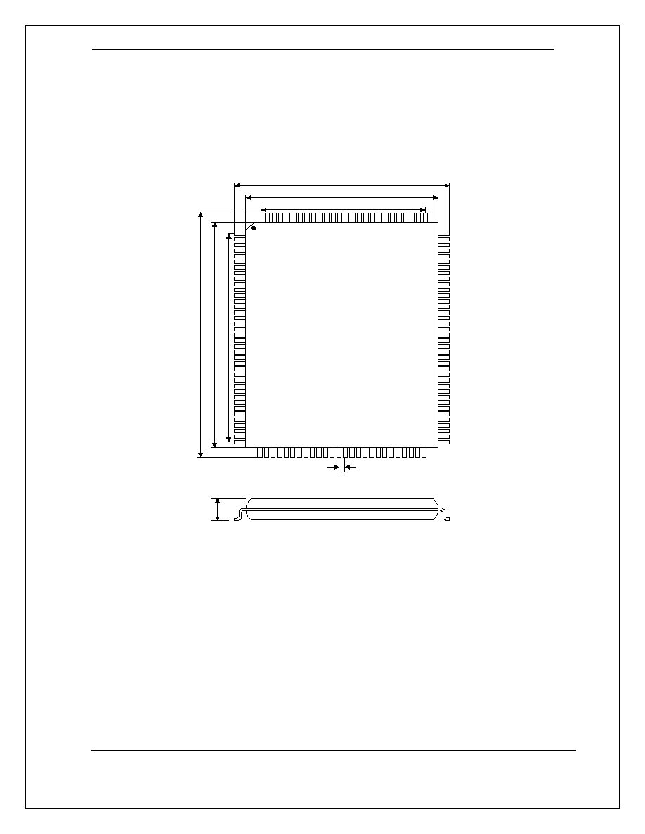
3.0 Package Outline and Dimensions
1
128 Pin PQ FP Package O utline D raw ing
12.5 m m
14.0 +/- 0.1 m m
17.2 +/- 0.2 m m
1
8
.5
m
m
2
0
.
0
+/
-
0.
1
m
m
2
3
.
2
+/
-
0.
2
m
m
0.5 m m
3.
4 m
m
ma
x
.
Figure - Package Outline
Thermal resistance
JA
= 32 ∞C/W

KS8993M (3 Port 10/100 Integrated Switch with PHY)
Micrel - Kendin Confidential Information Rev. 1.00 7/12/02
19
Micrel Inc. - Kendin Operations
486 Mercury Drive
Sunnyvale, CA 94085
© Micrel, Inc. 2001
All rights reserved
Micrel, Kendin are registered trademarks of Micrel and its subsidiaries in the
United States and certain other countries. All other trademarks are the property
of their respective owners.