 | –≠–ª–µ–∫—Ç—Ä–æ–Ω–Ω—ã–π –∫–æ–º–ø–æ–Ω–µ–Ω—Ç: MIC1810 | –°–∫–∞—á–∞—Ç—å:  PDF PDF  ZIP ZIP |

1
The MIC1810 is an inexpensive microprocessor
supervisory circuits that monitor power supplies in
microprocessor based systems.
The function of these devices is to assert a reset if the
power supply drops below a designated reset threshold
level. Several different reset threshold levels are
available to accomodate 5%, 10%, or 15% drop in 5V
powered systems.
The MIC1810 has an active low RESET output. The
reset output is guaranteed to remain asserted for a
minimum of 100ms after VCC has risen above the
designated reset threshold level. The MIC1810 comes
in a 3-pin SOT-23 package.
1
2
3
V
CC
GND
MIC1810
RESET
Top View
Part
Package
Temp. Range
MIC1810_U
3-Lead SOT23
-40∞C to +85∞C
Place the device suffix of desired reset threshold voltage from table above in
blank to complete the part number.
∑
Portable Equipment
∑
Intelligent Instruments
∑
Critical Microprocessor Power Monitoring
∑
Printers/Computers
∑
Controllers
∑
RESET Remains Valid with VCC as Low
as 1.4V
∑
Precision Voltage Monitor for 5%, 10%,
or 15% drop in 5V Power Supplies
∑
Available in 3-Pin SOT23 Package
∑
9
µ
A Supply Current (typical)
∑
100ms Minimum Reset Pulse Width
∑
No External Components Required
8++
4-5-6
µP
4-5-6
8++
MIC1810
8++
Typical Operating Circuit
Features
Description
Pin Configuration
Ordering Information
Typical Applications
Reset Threshold
Device
Voltage (V)
Suffix
4.62
-5
4.37
-10
4.12
-15
MIC1810 Microprocessor Reset Circuit
MIC1810
Microprocessor Reset Circuit

MIC1810 Microprocessor Reset Circuit
2
Electrical Characteristics
VCC = 5V, T
A
= Operating Temperature Range, unless otherwise noted.
Parameter
Conditions
Min
Typ
Max
Units
Operating Voltage Range, VCC TA = 0∞C to 70∞C
1.4
5.5
V
TA = -40∞C to 85∞C
1.6
5.5
Supply Current, ICC
9
20
µ
A
Reset Voltage Threshold, VTH
MIC1810-5
4.50
4.62
4.75
V
MIC1810-10
4.25
4.37
4.50
MIC1810-15
4.00
4.12
4.24
Reset Timeout Period
100
150
250
ms
RESET Output Voltage, VOH
ISource = 800
µ
A
VCC - 1.5V
V
RESET Output Voltage, VOL
VCC=VTH Min., ISink=3.2mA
0.4
V
VCC>1.4V, ISink =50
µ
A
0.3
Stresses above those listed under ABSOLUTE MAXIMUM RATINGS may cause permanent device failure. Functionality at or above these limits is not implied. Exposure to absolute
maximum ratings for extended periods may affect device reliability. Operating ranges define those limits between which the functionality of the device is guaranteed.
Absolute Maximum Ratings
Terminal Voltage
VCC . . . . . . . . . . . . . . . . . . . . . . . . . . . -0.3V to 6.0V
Input Current, VCC, . . . . . . . . . . . . . . . . . . . . . . . 20mA
Output Current, RESET . . . . . . . . . . . . . .
20mA
Rate of Rise, VCC . . . . . . . . . . . . . . . . . . . . . . 100V/
µ
s
Operating Temperature Range
MIC1810-U . . . . . . . . . . . . . . . . . . . . . . . . -40∞C to 85∞C
Storage Temperature Range . . . . . . . . . . . . .-65∞C to 150∞C
Lead Temperature (Soldering - 10 sec.) . . . . . . . . . . . 300∞C
Power Dissipation (TA = +70∞C) . . . . . . . . . . . . . . . . 320mW

MIC1810 Microprocessor Reset Circuit
Pin Functions
3
RESET goes low if VCC falls below the reset threshold and remains asserted for one
reset timeout period (100ms min.) after VCC exceeds the reset threshold.
Power supply input, 5V.
IC Ground Pin.
Pin Name
Pin No.
RESET
1
VCC
2
GND
3
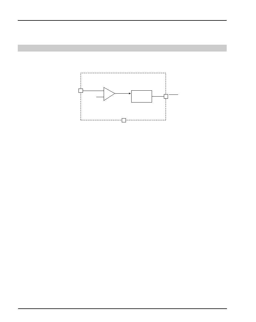
4
+
-
Reset
Threshold (VTH)
VCC (2)
RESET (1)
GND (3)
RESET
GENERATOR
Figure 1. MIC1810 Block Diagram
Block Diagram
MIC1810 Microprocessor Reset Circuit

5
Microprocessor Reset
The RESET pin is asserted whenever VCC falls below
the reset threshold voltage. The reset pin remains
asserted for a period of 150ms after VCC has risen
above the reset threshold voltage. The reset function
ensures the microprocessor is properly reset and powers
up into a known condition after a power failure. RESET
will remain valid with VCC as low as 1.4V.
VCC Transients
The MIC1810 is relatively immune to negative-going
VCC glitches below the reset threshold. Typically, a
negative-going transient 125mV below the reset
threshold with a duration of 50
µ
s or less will not cause
an unwanted reset.
RESET Valid to 0V
A resistor can be added from the RESET pin to ground
to ensure the RESET output remains low with VCC
down to 0V. A 100K
resistor connected from RESET
to ground is recommended. The size of the resistor
should be large enough to not load the RESET output
and small enough to pull-down any stray leakage
currents.
Circuit Description
Figure 2. Reset Timing Diagram
Figure 3. RESET Valid to VCC = OV
8++
8JDH
4-5-6
J
J
8JDH
VCC
RESET
µP
RESET
VCC
MIC1810
VCC
100K
MIC1810 Microprocessor Reset Circuit

6
MIC Direct
Industry P/N
Replacement
DS1810R-5
MIC1810-5U
DS1810R-10
MIC1810-10U
DS1810R-15
MIC1810-15U
Alternate Source Cross Reference Guide
MIC1810 Microprocessor Reset Circuit

7
Packaging Information
0.079
0.071
0.120
0.105
0.040
0.031
0.004
0.001
0.021
0.015
0.055
0.047
0.098
0.083
0.0059
0.0035
0.010
0.005
0-8º
U Package, 3-Pin SOT-23 Small-Outline Transistor Package
Device Marking Information
Lot Code
XXXX = MIC1810-5U
XXXX = MIC1810-10U
XXXX = MIC1810-15U
Dimensions are in inches.
MIC1810 Microprocessor Reset Circuit
8
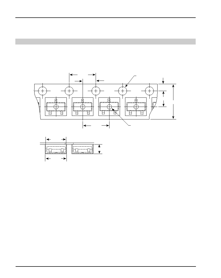
Packaging Information
4.0±0.1
4.0±0.1
2.0±0.05
3.5±0.05
8.0±0.3
1.75±0.1
Ø1.5±0.1
Ø1.1±0.1
2.7±0.1
3.1±0.1
1.2±0.1
Tape and Reel Information
Dimensions are in millimeters.
MIC1810 Microprocessor Reset Circuit