 | –≠–ª–µ–∫—Ç—Ä–æ–Ω–Ω—ã–π –∫–æ–º–ø–æ–Ω–µ–Ω—Ç: MIC2199 | –°–∫–∞—á–∞—Ç—å:  PDF PDF  ZIP ZIP |

November 2004
1
MIC2199
MIC2199
Micrel
MIC2199
300kHz 4mm ◊
◊
◊
◊
◊ 4mm Synchronous Buck Converter
General Description
The MIC2199 is a high-power 300kHz synchronous buck
DC-to-DC controller housed in a small 4mm ◊ 4mm MLFTM
12-lead package. The MIC2199 operates from a wide 4.5V to
32V input and can be programmed for output voltages from
0.8V to 6V. The wide input voltage capability makes the
MIC2199 an ideal solution for point-of-load DC-to-DC con-
version in 5V, 12V, 24V, and 28V systems.
The 300kHz switching frequency allows the use of a small
inductor and small output capacitors. The current mode PWM
control along with the external COMP pin allows for ease of
stability compensation and fast transient response across a
wide range of applications.
An all N-Channel synchronous architecture and powerful
output drivers allow up to 20A of output current capability.
For smaller external components, refer to the 500kHz
MIC2198.
The MIC2199 is available in a 12-pin 4mm ◊ 4mm MLFTM
package with a junction temperature range from ≠40∞C to
125∞C.
Features
∑ 4.5V to 32V input range
∑ 4mm ◊ 4mm MLFTM package
∑ 300kHz PWM operation
∑ 95% efficiency
∑ Output voltage adjustable down to 0.8V
∑ 20A output current capability
∑ Drives all N-Channel MOSFETs
∑ Logic controlled micropower shutdown
∑ Cycle-by-cycle current limiting
∑ Adjustable undervoltage lockout
∑ Frequency foldback overcurrent protection
Applications
∑ Point-of-load DC-to-DC conversion from 5V, 12V,
24V, 28V supplies
∑ Telecom equipment
∑ Wireless modems
∑ Servers
∑ Base stations
Micrel, Inc. ∑ 2180 Fortune Drive ∑ San Jose, CA 95131 ∑ USA ∑ tel + 1 (408) 944-0800 ∑ fax + 1 (408) 474-1000 ∑ http://www.micrel.com
MLF and
Micro
LeadFrame are trademarks of Amkor Technology, Inc.
Typical Application
IRF7821
IRF7821
2mH
0.01W
V
OUT
3.3V/7A
10kW
6.04kW
1nF
V
IN
4.5V to 24V
VIN
EN/UVLO
COMP
CSH
LSD
VSW
VDD
BST
HSD
GND
VOUT
FB
2.2nF
2kW
U1 MIC2199BML
SD103BWS
0.1mF
22mF
4.7mF
220mF
4.5V≠24V to 3.3V/7A Converter
85.0
90.0
95.0
100.0
0
2
4
6
8
EFFICIENCY (%)
I
LOAD
(A)
V
OUT
= 3.3V
Efficiency for
V
IN
= 5V and V
OUT
= 3.3V

MIC2199
Micrel
MIC2199
2
November 2004
Pin Configuration
1
2
3
4
COMP
EN/UVLO
FB
CSH
HSD
VSW
BST
GND
VOUT
VIN
5
6
12
11
10
9
8
7
LSD
VDD
4◊
◊
◊
◊
◊4 MLF-12L (ML)
Ordering Information
Part Number
Voltage
Temperature Range
Package
MIC2199BML
Adj
≠40∞C to +125∞C
12-lead 4◊4 MLFTM
Pin Description
Pin Number
Pin Name
Pin Function
1
COMP
Compensation (Output): Internal error amplifier output. Connect to capacitor
or series RC network to compensate the regulator control loop.
2
EN/UVLO
Enable/Undervoltage Lockout (Input): Low-level signal powers down the
controller. Input below the 2.5V threshold disables switching and functions
as an accurate undervoltage lockout (UVLO). Input below the threshold
forces complete micropower (<0.1µA) shutdown.
3
FB
Feedback (Input): Regulates FB pin to 0.8V. See
"Applications Information"
for resistor divider calculations.
4
CSH
Current-Sense High (Input): Current limit comparator non-inverting input. A
built-in offset of 100mV between CSH and V
OUT
pins in conjunction with the
current-sense resistor set the current limit threshold level. This is also the
non-inverting input to the current sense amplifier.
5
VOUT
Current-Sense Low (Input): Output voltage feedback input and inverting
input for the current limit comparator and the current sense amplifier.
6
VIN
Unregulated Input (Input): +4.5V to +32V supply input.
7
VDD
5V Internal Linear-Regulator (Output): V
DD
is the external MOSFET gate
drive supply voltage and internal supply bus for the IC. Bypass to GND with
4.7µF.
8
LSD
Low-Side Drive (Output): High-current driver output for low-side N-Channel
MOSFET. Voltage swing is between ground and V
DD
.
9
GND
Ground (Return).
10
BST
Boost (Input): Provides drive voltage for the high-side MOSFET driver. The
drive voltage is higher than the input voltage by V
DD
minus a diode drop.
11
VSW
Switch (Return): High-side MOSFET driver return.
12
HSD
High-Side Drive (Output): High-current driver output for high-side MOSFET.
This node voltage swing is between ground and V
IN
+5V minus a diode drop.
November 2004
3
MIC2199
MIC2199
Micrel
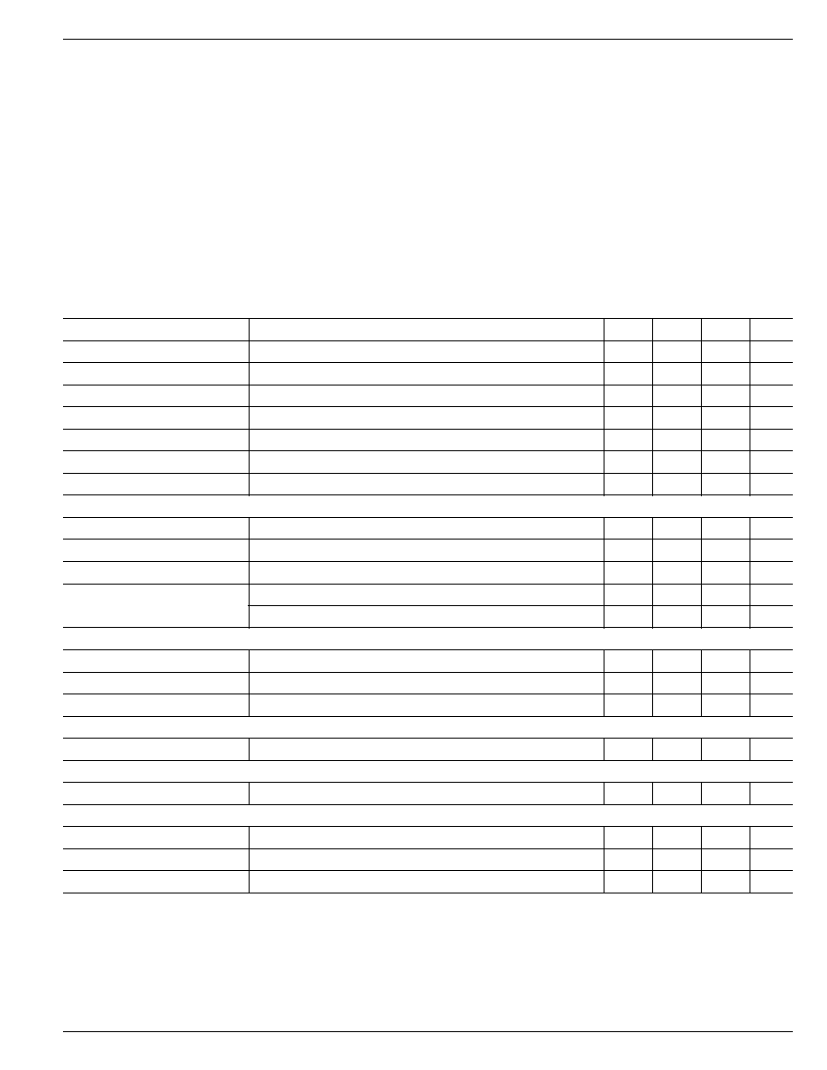
Electrical Characteristics
(Note 4)
V
IN
= V
EN
= 12V; T
J
= 25∞C, unless noted, bold values indicate ≠40∞C T
J
+125∞C
Parameter
Condition
Min
Typ
Max
Units
Feedback Voltage Reference
(±1%)
0.792
0.8
0.808
V
Feedback Voltage Reference
(±2%)
0.784
0.816
V
Feedback Voltage Reference
4.5V < V
IN
< 32V, 0 < (V
CSH
≠ V
OUT
) < 60mV (±3%)
0.776
0.824
V
Feedback Bias Current
10
nA
Output Voltage Range
0.8
6
V
Output Voltage Line Regulation
V
IN
= 4.5V to 32V, V
CSH
≠ V
OUT
= 60mV
0.03
%/V
Output Voltage Load Regulation
25mV < (V
CSH
≠ V
OUT
) < 60mV
0.5
%
Input and V
DD
Supply
Quiescent Current
excluding external MOSFET gate drive current
1.6
2.5
mA
Shutdown Quiescent Current
V
EN/UVLO
= 0V
0.1
5
µA
Digital Supply Voltage (V
DD
)
I
L
= 0mA to 5mA
4.7
5.0
5.3
V
Undervoltage Lockout
V
IN
upper threshold (turn-on threshold)
4.25
4.4
V
V
IN
lower threshold (turn-off threshold)
3.95
4.1
V
Enable/UVLO
Enable Input Threshold
0.6
1.1
1.6
V
UVLO Threshold
2.2
2.5
2.8
V
Enable Input Current
V
EN/UVLO
= 5V
0.1
5
µA
Current Limit
Current Limit Threshold Voltage
(V
CSH
≠ V
OUT
)
55
75
95
mV
Error Amplifier
Transconductance Error Amplifier GM
0.2
mS
Oscillator Section
Oscillator Frequency
270
300
330
kHz
Maximum Duty Cycle
80
85
%
Minimum On-Time
170
200
ns
Absolute Maximum Ratings
(Note 1)
Analog Supply Voltage (V
IN
) ....................................... +34V
Digital Supply Voltage (V
DD
) ......................................... +7V
Driver Supply Voltage (B
ST
) .................................. V
IN
+ 7V
Sense Voltage (V
OUT
, C
SH
) ............................. 7V to ≠0.3V
Enable Pin Voltage (V
EN/UVLO
) ...................................... V
IN
Power Dissipation (P
D
)
4◊4 MLFTM ................................. 665mW @ T
A
= 85∞C
Ambient Storage Temperature (T
S
) ......... ≠65∞C to +150∞C
ESD, Note 3
Operating Ratings
(Note 2)
Analog Supply Voltage (V
IN
) ........................ +4.5V to +32V
Output Voltage Range (V
OUT
) ........................ +0.8V to +6V
Junction Temperature (T
J
) ....................... ≠40∞C to +125∞C
Package Thermal Resistance
4◊4 MLF-12L (
JA
) .............................................. 60∞C/W

MIC2199
Micrel
MIC2199
4
November 2004
Parameter
Condition
Min
Typ
Max
Units
Frequency Foldback Threshold
measured at V
OUT
pin
0.25
0.40
0.55
V
Foldback Frequency
75
kHz
Gate Drivers
Rise/Fall Time
C
L
= 3000pF
60
ns
Output Driver Impedance
source
5
8.5
sink
3.5
6
Driver Non-Overlap Time
80
ns
Note 1.
Exceeding the absolute maximum rating may damage the device.
Note 2.
The device is not guaranteed to function outside its operating rating.
Note 3.
Devices are ESD protected; however, handling precautions are recommended. Human body model, 1.5k in series with 100pF.
Note 4.
Specification for packaged product only.
November 2004
5
MIC2199
MIC2199
Micrel
0
0.5
1.0
1.5
2.0
2.5
3.0
3.5
4.0
-40 -20 0 20 40 60 80 100120140
CURRENT (mA)
TEMPERATURE (∞C)
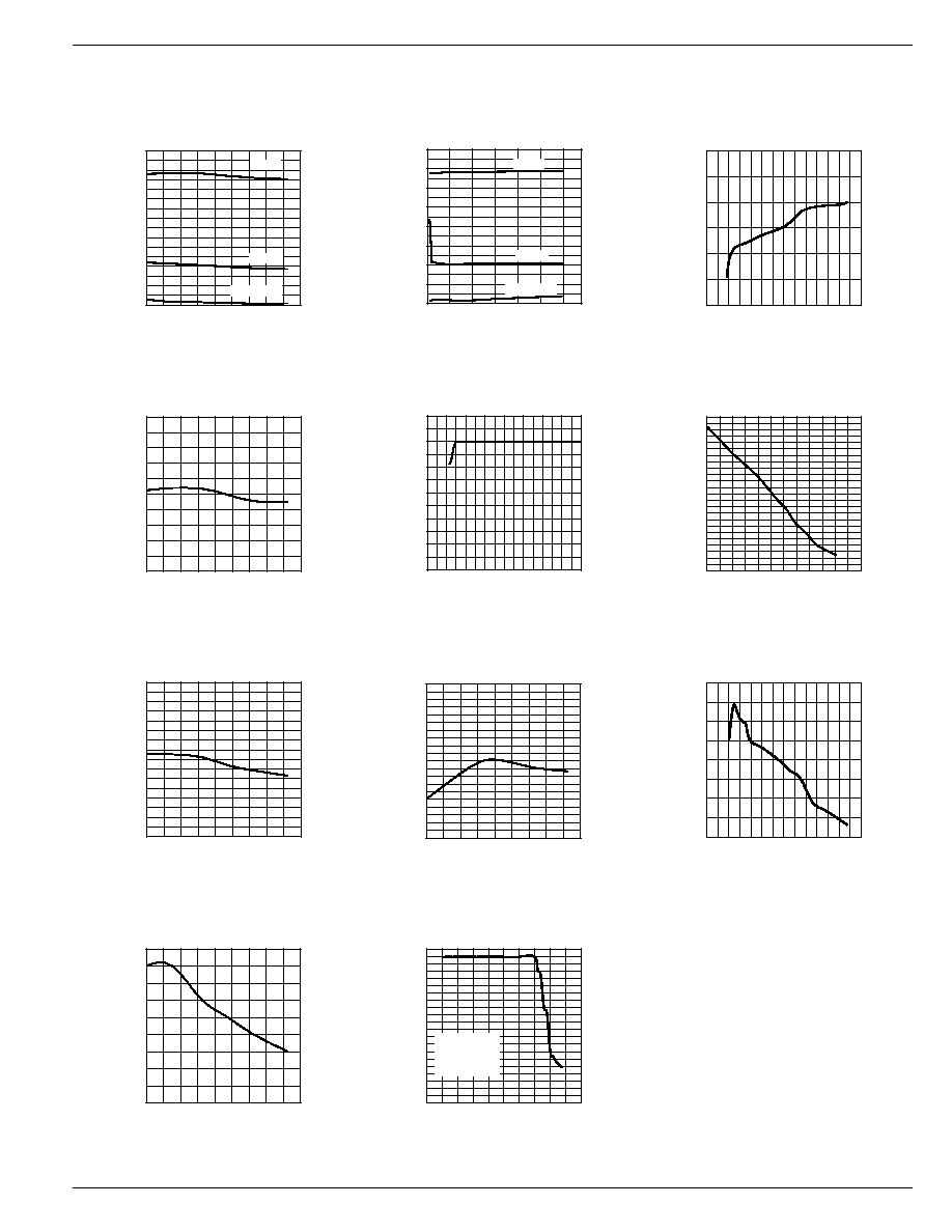
Quiescent Current
vs. Temperature
PWM
UVLO
Shutdown
0
0.5
1.0
1.5
2.0
2.5
3.0
3.5
4.0
4
9
14
19
24
29
34
QUIESCENT CURRENT (mA)
SUPPLY VOLTAGE (V)
Quiescent Current
vs. Supply Voltage
PWM
UVLO
Shutdown
0.808
0.810
0.812
0.814
0.816
0.818
0.820
0
5
10
15
20
25
30
35
REFERENCE VOLTAGE (V)
SUPPLY VOLTAGE (V)
V
FB
Line Regulation
0.8
0.802
0.804
0.806
0.808
0.810
0.812
0.814
0.816
0.818
0.82
-40 -20 0 20 40 60 80 100120140
FB VOLTAGE (V)
TEMPERATURE (∞C)
V
FB
vs. Temperature
4.94
4.95
4.96
4.97
4.98
4.99
5.00
5.01
5.02
0
5
10
15
20
25
30
V
DD
REGULATOR VOLTAGE (V)
LOAD CURRENT (mA)
V
DD
Load Regulation
4.80
4.85
4.90
4.95
5.00
5.05
5.10
5.15
5.20
-40 -20 0 20 40 60 80 100120140
V
DD
REGULATOR VOLTAGE (V)
TEMPERATURE (∞C)
V
DD
vs. Temperature
-10
-8
-6
-4
-2
0
2
4
6
8
10
-40 -20 0 20 40 60 80 100120140
FREQUENCY VARIATION (%)
TEMPERATURE (∞C)
Oscillator Frequency
vs. Temperature
-0.15
-0.10
-0.05
0.00
0.05
0.10
0.15
0.20
0.25
0
5
10
15
20
25
30
35
FREQUENCY VARIATION (%)
SUPPLY VOLTAGE (V)
Oscillator Frequency
vs. Supply Voltage
Typical Characteristics
70
72
74
76
78
80
82
84
86
88
-40 -20 0 20 40 60 80 100120140
OVERCURRENT THRESHOLD (V)
TEMPERATURE (∞C)
Overcurrent Threshold
vs. Temperature
0
0.5
1
1.5
2
2.5
3
3.5
0
1
2
3
4
5
OUTPUT VOLTAGE (V)
OUTPUT CURRENT (A)
Current Limit
Foldback
V
IN
= 5V
V
OUT
= 3.3V
R
CS
= 20mV
0.0
1.0
2.0
3.0
4.0
5.0
6.0
0
4
8
12 16 20 24 28 32
V
DD
REGULATOR VOLTAGE (V)
SUPPLY VOLTAGE (V)
V
DD
Line Regulation

MIC2199
Micrel
MIC2199
6
November 2004
Block Diagram
G
m
= 0.2◊10
-3
Current
Limit
V
BG
0.8V
V
BG
Error
Amp
V
IN
V
DD
PWM OUTPUT
CORRECTIVE
RAMP
RESET
Reference
Oscillator
EN/UVLO
2
7
10
6
12
11
8
9
4
5
3
1
COMP
100k
MIC2199
FB
R2
R1
VOUT
CSH
VDD
BST
C
IN
VIN
HSD
Q2
Q1
D1
D2
C
BST
C
OUT
V
IN
V
OUT
L1
VSW
LSD
PGND
C
COMP
R
COMP
4.7µF
A
V
= 2
V
0.8V
R1
R2
OUT
=
+
1
V
6 V
OUT(max)
= .0
Current
Sense
Amp
R
CS
Control
Logic
PWM
Figure 1. Internal Block Diagram
Functional Description
The MIC2199 is a BiCMOS, switched-mode, synchronous
step-down (buck) converter controller. Current-mode control
is used to achieve superior transient line and load regulation.
An internal corrective ramp provides slope compensation for
stable operation above a 50% duty cycle. The controller is
optimized for high-efficiency, high-performance DC-DC con-
verter applications.
The MIC2199 block diagram is shown above.
The MIC2199 controller is divided into 5 functions.
∑ Control loop
∑ Current limit
∑ Reference, enable and UVLO
∑ MOSFET gate drive
∑ Oscillator
Control Loop
The MIC2199 operates in PWM (pulse-width-modulation)
mode. In PWM mode, the synchronous buck converter forces
continuous current to flow in the inductor which also improves
cross regulation of transformer coupled, multiple output con-
figurations.
PWM Control Loop
The MIC2199 uses current-mode control to regulate the
output voltage. This method senses the output voltage (outer
loop) and the inductor current (inner loop). It uses inductor
current and output voltage to determine the duty cycle of the
buck converter. Sampling the inductor current removes the
inductor from the control loop, which simplifies compensa-
tion.
A block diagram of the MIC2199 PWM current-mode control
loop is shown in Figure 2 and the PWM mode voltage and
current waveform is shown in Figure 3. The inductor current
is sensed by measuring the voltage across the resistor, R
CS
.

November 2004
7
MIC2199
MIC2199
Micrel
A ramp is added to the amplified current-sense signal to
provide slope compensation, which is required to prevent
unstable operation at duty cycles greater than 50%.
A transconductance amplifier is used for the error amplifier,
which compares an attenuated sample of the output voltage
with a reference voltage. The output of the error amplifier is
the COMP (compensation) pin, which is compared to the
current-sense waveform in the PWM block. When the current
signal becomes greater than the error signal, the comparator
turns off the high-side drive. The COMP pin (pin 1) provides
access to the output of the error amplifier and allows the use
of external components to stabilize the voltage loop.
Current
Sense
Amp
V
BG
0.8V
V
BG
Error
Amp
V
IN
V
DD
CORRECTIVE
RAMP
PWM
COMPARATOR
RESET
Oscillator
7
10
6
12
11
8
9
4
5
3
1
COMP
100k
MIC2199
FB
R2
R1
VOUT
CSH
VDD
BST
C
IN
VIN
HSD
Q2
Q1
D1
D2
C
BST
C
OUT
V
IN
V
OUT
L1
VSW
LSD
PGND
C
COMP
R
COMP
4.7µF
S
R
Q
CONTROL LOGIC AND
PULSE-WIDTH MODULATOR
R
CS
G
m
= 0.2◊10
-3
A
V
= 2
V
0.8V
R1
R2
OUT
=
+
1
Reference
Figure 2. PWM Operation
V
DD
0V
0V
0V
0V
0A
V
DD
V
IN
+ V
DD
V
IN
V
SW
Reset
Pulse
V
HSD
V
LSD
I
LOAD
I
L1
Figure 3. PWM-Mode Timing

MIC2199
Micrel
MIC2199
8
November 2004
Current Limit
The MIC2199 output current is detected by the voltage drop
across the external current-sense resistor (R
CS
in Figure 2.).
The current limit threshold is 75mV±20mV. The current-
sense resistor must be sized using the minimum current limit
threshold. The external components must be designed to
withstand the maximum current limit. The current-sense
resistor value is calculated by the equation below:
R
55mV
I
CS
OUT(max)
=
The maximum output current is:
I
95mV
R
OUT(max)
CS
=
The current-sense pins CSH (pin 4) and V
OUT
(pin 5) are
noise sensitive due to the low signal level and high input
impedance. The PCB traces should be short and routed close
to each other. A small (1nF to 0.1µF) capacitor across the
pins will attenuate high frequency switching noise.
When the peak inductor current exceeds the current limit
threshold, the current limit comparator, in Figure 2, turns off
the high-side MOSFET for the remainder of the cycle. The
output voltage drops as additional load current is pulled from
the converter. When the output voltage reaches approxi-
mately 0.4V, the circuit enters frequency-foldback mode and
the oscillator frequency will drop to 75kHz while maintaining
the peak inductor current equal to the nominal 75mV across
the external current-sense resistor. This limits the maximum
output power delivered to the load under a short circuit
condition.
Reference, Enable and UVLO Circuits
The output drivers are enabled when the following conditions
are satisfied:
∑ The V
DD
voltage (pin 7) is greater than its under-
voltage threshold (typically 4.25V).
∑ The voltage on the enable pin is greater than the
enable UVLO threshold (typically 2.5V).
The internal bias circuit generates a 0.8V bandgap reference
voltage for the voltage error amplifier and a 5V V
DD
voltage
for the gate drive circuit. The MIC2199 uses FB (pin 3) for
output voltage sensing.
The enable pin (pin 2) has two threshold levels, allowing the
MIC2199 to shut down in a low current mode, or turn off output
switching in UVLO mode. An enable pin voltage lower than
the shutdown threshold turns off all the internal circuitry and
reduces the input current to typically 0.1µA.
If the enable pin voltage is between the shutdown and UVLO
thresholds, the internal bias, V
DD
, and reference voltages are
turned on. The output drivers are inhibited from switching and
remain in a low state. Raising the enable voltage above the
UVLO threshold of 2.5V enables the output drivers.
Either of two UVLO conditions will disable the MIC2199 from
switching.
∑ When the V
DD
drops below 4.1V
∑ When the enable pin drops below the 2.5V threshold
MOSFET Gate Drive
The MIC2199 high-side drive circuit is designed to switch an
N-Channel MOSFET. Referring to the block diagram in
Figure 2, a bootstrap circuit, consisting of D2 and C
BST
,
supplies energy to the high-side drive circuit. Capacitor C
BST
is charged while the low-side MOSFET is on and the voltage
on the V
SW
pin (pin 11) is approximately 0V. When the high-
side MOSFET driver is turned on, energy from C
BST
is used
to turn the MOSFET on. As the MOSFET turns on, the voltage
on the V
SW
pin increases to approximately V
IN
. Diode D2 is
reversed biased and C
BST
floats high while continuing to
keep the high-side MOSFET on. When the low-side switch is
turned back on, C
BST
is recharged through D2.
The drive voltage is derived from the internal 5V V
DD
bias
supply. The nominal low-side gate drive voltage is 5V and the
nominal high-side gate drive voltage is approximately 4.5V
due the voltage drop across D2. A fixed 80ns delay between
the high- and low-side driver transitions is used to prevent
current from simultaneously flowing unimpeded through both
MOSFETs.
Oscillator
The internal oscillator is free running and requires no external
components. The nominal oscillator frequency is 500kHz. If
the output voltage is below approximately 0.4V, the oscillator
operates in a frequency-foldback mode and the switching
frequency is reduced to 75kHz.
V
SS
TIME
f
S
= 75kHz
V
OUT
= 0.4V
f
S
= 300kHz
V
IN
= 7V
V
OUT
= 3.3V
Figure 4. Startup Waveform
Above 0.4V, the switching frequency increases to 500kHz
causing the output voltage to rise a greater rate. The rise time
of the output is dependent on the output capacitance, output
voltage, and load current. The oscilloscope photo in Figure 4
show the output voltage at startup.
November 2004
9
MIC2199
MIC2199
Micrel
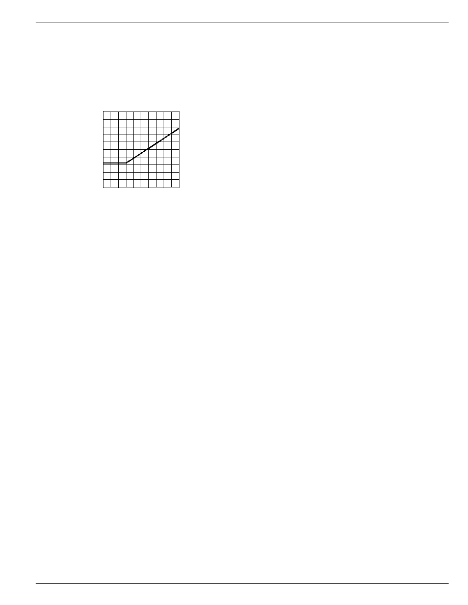
Minimum Pulsewidth
The MIC2199 has a specified minimum pulsewidth. This
minimum pulsewidth places a lower limit on the minimum duty
cycle of the buck converter.
Figure 5 shows the minimum output voltage versus input
supply voltage for the MIC2199. For example, for V
IN
= 15V,
V
OUT
= 1V would be the lowest achievable voltage that
conforms to the minimum-on-time.
0.0
0.5
1.0
1.5
2.0
2.5
4.5
9.5
14.5
19.5
24.5
29.5
OUTPUT VOLTAGE (V)
INPUT VOLTAGE (V)
Figure 5. Minimum Output Voltage
vs. Input Supply Voltage

MIC2199
Micrel
MIC2199
10
November 2004
Applications Information
Following applications information includes component se-
lection and design guidelines.
Inductor Selection
Values for inductance, peak, and RMS currents are required
to select the output inductor. The input and output voltages
and the inductance value determine the peak-to-peak induc-
tor ripple current. Generally, higher inductance values are
used with higher input voltages. Larger peak-to-peak ripple
currents will increase the power dissipation in the inductor
and MOSFETs. Larger output ripple currents will also require
more output capacitance to smooth out the larger ripple
current. Smaller peak-to-peak ripple currents require a larger
inductance value and therefore a larger and more expensive
inductor. A good compromise between size, loss and cost is
to set the inductor ripple current to be equal to 20% of the
maximum output current.
The inductance value is calculated by the equation below.
L
V
(V
V
)
V
f
0.2 I
OUT
IN(max)
OUT
IN(max)
S
OUT(max)
=
◊
-
◊
◊
◊
where:
f
S
= switching frequency
0.2 = ratio of AC ripple current to DC output current
V
IN(max)
= maximum input voltage
The peak-to-peak inductor current (AC ripple current) is:
I
V
(V
V
)
V
f
L
PP
OUT
IN(max)
OUT
IN(max)
S
=
◊
-
◊
◊
The peak inductor current is equal to the average output
current plus one half of the peak-to-peak inductor ripple
current.
I
I
0.5 I
PK
OUT(max)
PP
=
+
◊
The RMS inductor current is used to calculate the I
2
◊R losses
in the inductor.
I
I
1
1
3
I
I
INDUCTOR(rms)
OUT(max)
P
OUT(max)
2
=
◊
+
Maximizing efficiency requires the proper selection of core
material and minimizing the winding resistance. The high
frequency operation of the MIC2199 requires the use of ferrite
materials for all but the most cost sensitive applications.
Lower cost iron powder cores may be used but the increase
in core loss will reduce the efficiency of the power supply. This
is especially noticeable at low output power. The winding
resistance decreases efficiency at the higher output current
levels. The winding resistance must be minimized although
this usually comes at the expense of a larger inductor.
The power dissipated in the inductor is equal to the sum of the
core and copper losses. At higher output loads, the core
losses are usually insignificant and can be ignored. At lower
output currents, the core losses can be a significant contribu-
tor. Core loss information is usually available from the mag-
netics vendor.
Copper loss in the inductor is calculated by the equation
below:
P
I
R
INDUCTORCu
INDUCTOR(rms)
WINDING
2
=
◊
The resistance of the copper wire, R
WINDING
, increases with
temperature. The value of the winding resistance used should
be at the operating temperature.
R
R
1 0.0042 (T
T
)
WINDING(hot)
WINDING(20 C)
HOT
20 C
=
◊
+
◊
-
(
)
∞
∞
where:
T
HOT
= temperature of the wire under operating load
T
20∞C
= ambient temperature
R
WINDING(20∞C)
is room temperature winding resistance
(usually specified by the manufacturer)
Current-Sense Resistor Selection
Low inductance power resistors, such as metal film resistors
should be used. Most resistor manufacturers make low
inductance resistors with low temperature coefficients, de-
signed specifically for current-sense applications. Both resis-
tance and power dissipation must be calculated before the
resistor is selected. The value of R
SENSE
is chosen based on
the maximum output current and the maximum threshold
level. The power dissipated is based on the maximum peak
output current at the minimum overcurrent threshold limit.
R
55mV
I
SENSE
OUT(max)
=
The maximum overcurrent threshold is:
I
95mV
R
OVERCURRENT(max)
CS
=
The maximum power dissipated in the sense resistor is:
P
I
R
D(R
)
OVERCURRENT(max)
2
CS
SENSE
=
◊
MOSFET Selection
External N-Channel logic-level power MOSFETs must be
used for the high- and low-side switches. The MOSFET gate-
to-source drive voltage of the MIC2199 is regulated by an
internal 5V V
DD
regulator. Logic-level MOSFETs, whose
operation is specified at V
GS
= 4.5V must be used.
It is important to note the on-resistance of a MOSFET
increases with increasing temperature. A 75∞C rise in junc-
tion temperature will increase the channel resistance of the
MOSFET by 50% to 75% of the resistance specified at 25∞C.
This change in resistance must be accounted for when
calculating MOSFET power dissipation.
Total gate charge is the charge required to turn the MOSFET
on and off under specified operating conditions (V
DS
and
V
GS
). The gate charge is supplied by the MIC2199 gate drive
circuit. At 500kHz switching frequency, the gate charge can
be a significant source of power dissipation in the MIC2199.
At low output load this power dissipation is noticeable as a

November 2004
11
MIC2199
MIC2199
Micrel
reduction in efficiency. The average current required to drive
the high-side MOSFET is:
I
Q
f
G[high-side](avg)
G
S
=
◊
where:
I
G[high-side](avg)
=
average high-side MOSFET gate current
Q
G
= total gate charge for the high-side MOSFET
taken from manufacturer's data sheet
with V
GS
= 5V.
f
s
= 300kHz
The low-side MOSFET is turned on and off at V
DS
= 0
because the freewheeling diode is conducting during this
time. The switching losses for the low-side MOSFET is
usually negligible. Also, the gate drive current for the low-side
MOSFET is more accurately calculated using C
ISS
at V
DS
=
0 instead of gate charge.
For the low-side MOSFET:
I
C
V
f
G[low-side](avg)
ISS
GS
S
=
◊
◊
Since the current from the gate drive comes from the input
voltage, the power dissipated in the MIC2199 due to gate
drive is:
P
V
I
I
GATEDRIVE
IN G[high-side](avg)
G[low-side](avg)
=
+
(
)
A convenient figure of merit for switching MOSFETs is the on-
resistance times the total gate charge (R
DS(on)
◊ Q
G
). Lower
numbers translate into higher efficiency. Low gate-charge
logic-level MOSFETs are a good choice for use with the
MIC2199. Power dissipation in the MIC2199 package limits
the maximum gate drive current.
Parameters that are important to MOSFET switch selection
are:
∑ Voltage rating
∑ On-resistance
∑ Total gate charge
The voltage rating of the MOSFETs are essentially equal to
the input voltage. A safety factor of 20% should be added to
the V
DS(max)
of the MOSFETs to account for voltage spikes
due to circuit parasitics.
The power dissipated in the switching transistor is the sum of
the conduction losses during the on-time (P
CONDUCTION
) and
the switching losses that occur during the period of time when
the MOSFETs turn on and off (P
AC
).
P
P
P
SW
CONDUCTION
AC
=
+
where:
P
I
R
CONDUCTION
SW(rms)
SW
2
=
◊
P
P
P
AC
AC(off)
AC(on)
=
+
R
SW
= on-resistance of the MOSFET switch.
Making the assumption the turn-on and turnoff transition
times are equal, the transition time can be approximated by:
t
C
V
C
V
I
T
ISS
GS
OSS
IN
G
=
◊
+
◊
where:
C
ISS
and C
OSS
are measured at V
DS
= 0.
I
G
= gate drive current (1A for the MIC2199)
The total high-side MOSFET switching loss is:
P
(V
V ) I
t
f
AC
IN
D
PK
T
S
=
+
◊
◊
◊
where:
t
T
= switching transition time (typically 20ns to 50ns)
V
D
= freewheeling diode drop, typically 0.5V.
f
S
it the switching frequency, nominally 300kHz
The low-side MOSFET switching losses are negligible and
can be ignored for these calculations.
RMS Current and MOSFET Power Dissipation
Calculation
Under normal operation, the high-side MOSFETs RMS cur-
rent is greatest when V
IN
is low (maximum duty cycle). The
low-side MOSFETs RMS current is greatest when V
IN
is high
(minimum duty cycle). However, the maximum stress the
MOSFETs see occurs during short circuit conditions, where
the output current is equal to I
OVERCURRENT(max)
. (See the
"Sense Resistor"
section). The calculations below are for
normal operation. To calculate the stress under short circuit
conditions, substitute I
OVERCURRENT(max)
for I
OUT(max)
. Use
the formula below to calculate D under short circuit condi-
tions.
D
0.063 1.8 10
V
SHORTCIRCUIT
3
IN
=
-
◊
◊
-
The RMS value of the high-side switch current is:
I
D
I
I
12
SW(high side)(rms)
OUT(max)
2
PP
2
-
=
◊
+
I
1 D I
I
12
SW(low side)(rms)
OUT(max)
2
PP
2
-
=
-
(
)
+
where:
D = duty cycle of the converter
D
V
V
OUT
IN
=
◊
= efficiency of the converter.
Converter efficiency depends on component parameters,
which have not yet been selected. For design purposes, an
efficiency of 90% can be used for V
IN
less than 10V and 85%
can be used for V
IN
greater than 10V. The efficiency can be
more accurately calculated once the design is complete. If the
assumed efficiency is grossly inaccurate, a second iteration
through the design procedure can be made.

MIC2199
Micrel
MIC2199
12
November 2004
For the high-side switch, the maximum DC power dissipation
is:
P
R
I
SWITCH1(dc)
DS(on)1
SW1(rms)
2
=
◊
For the low-side switch (N-Channel MOSFET), the DC power
dissipation is:
P
R
I
SWITCH2(dc)
DS(on)2
SW 2(rms)
2
=
◊
Since the AC switching losses for the low side MOSFET is
near zero, the total power dissipation is:
P
P
low-side MOSFET(max)
SWITCH2(dc)
=
The total power dissipation for the high side MOSFET is:
P
P
P
high sideMOSFET(max)
SWITCH 1(dc)
AC
-
=
+
External Schottky Diode
An external freewheeling diode is used to keep the inductor
current flow continuous while both MOSFETs are turned off.
This dead time prevents current from flowing unimpeded
through both MOSFETs and is typically 80ns The diode
conducts twice during each switching cycle. Although the
average current through this diode is small, the diode must be
able to handle the peak current.
I
I
2
80ns
f
D(avg)
OUT
S
=
◊ ◊
◊
The reverse voltage requirement of the diode is:
V
V
DIODE(rrm)
IN
=
The power dissipated by the Schottky diode is:
P
I
V
DIODE
D(avg)
F
=
◊
where:
V
F
= forward voltage at the peak diode current
The external Schottky diode, D2, is not necessary for circuit
operation since the low-side MOSFET contains a parasitic
body diode. The external diode will improve efficiency and
decrease high frequency noise. If the MOSFET body diode is
used, it must be rated to handle the peak and average current.
The body diode has a relatively slow reverse recovery time
and a relatively high forward voltage drop. The power lost in
the diode is proportional to the forward voltage drop of the
diode. As the high-side MOSFET starts to turn on, the body
diode becomes a short circuit for the reverse recovery period,
dissipating additional power. The diode recovery and the
circuit inductance will cause ringing during the high-side
MOSFET turn-on.
An external Schottky diode conducts at a lower forward
voltage preventing the body diode in the MOSFET from
turning on. The lower forward voltage drop dissipates less
power than the body diode. The lack of a reverse recovery
mechanism in a Schottky diode causes less ringing and less
power loss. Depending on the circuit components and oper-
ating conditions, an external Schottky diode will give a 1/2%
to 1% improvement in efficiency.
Output Capacitor Selection
The output capacitor values are usually determined by the
capacitors ESR (equivalent series resistance). Voltage rating
and RMS current capability are two other important factors in
selecting the output capacitor. Recommended capacitors are
tantalum, low-ESR aluminum electrolytics, and OS-CON.
The output capacitor's ESR is usually the main cause of
output ripple. The maximum value of ESR is calculated by:
R
V
I
ESR
OUT
PP
where:
V
OUT
= peak-to-peak output voltage ripple
I
PP
= peak-to-peak inductor ripple current
The total output ripple is a combination of the ESR and the
output capacitance. The total ripple is calculated below:
V
I
(1 D)
C
f
I
R
OUT
PP
OUT
S
2
PP
ESR
2
=
◊
-
◊
+
◊
(
)
where:
D = duty cycle
C
OUT
= output capacitance value
f
S
= switching frequency
The voltage rating of capacitor should be twice the output
voltage for a tantalum and 20% greater for an aluminum
electrolytic or OS-CON.
The output capacitor RMS current is calculated below:
I
I
12
C
PP
OUT(rms)
=
The power dissipated in the output capacitor is:
P
I
R
DISS(C
C
ESR(C
)
OUT
OUT(rms)2
OUT
)
=
◊
Input Capacitor Selection
The input capacitor should be selected for ripple current
rating and voltage rating. Tantalum input capacitors may fail
when subjected to high inrush currents, caused by turning the
input supply on. Tantalum input capacitor voltage rating
should be at least 2 times the maximum input voltage to
maximize reliability. Aluminum electrolytic, OS-CON, and
multilayer polymer film capacitors can handle the higher
inrush currents without voltage derating.
The input voltage ripple will primarily depend on the input
capacitors ESR. The peak input current is equal to the peak
inductor current, so:
V
I
R
IN
INDUCTOR(peak)
ESR(C )
IN
=
◊
November 2004
13
MIC2199
MIC2199
Micrel
The input capacitor must be rated for the input current ripple.
The RMS value of input capacitor current is determined at the
maximum output current. Assuming the peak-to-peak induc-
tor ripple current is low:
I
I
D (1 D)
C (rms)
OUT(max)
IN
◊
◊
-
The power dissipated in the input capacitor is:
P
I
R
DISS(C )
C (rms)
ESR(C )
IN
IN
2
IN
=
◊
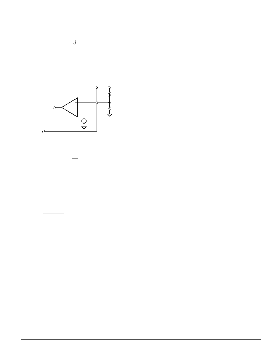
Voltage Setting Components
The MIC2199 requires two resistors to set the output voltage
as shown in Figure 6.
Error
Amp
3
MIC2199
FB
V
REF
0.8V
R2
R1
Figure 6. Voltage-Divider Configuration
The output voltage is determined by the equation:
V
V
1
R1
R2
O
REF
=
◊
+
Where: V
REF
for the MIC2199 is typically 0.8V.
A typical value of R1 can be between 3k and 10k. If R1 is too
large it may allow noise to be introduced into the voltage
feedback loop. If R1 is too small in value it will decrease the
efficiency of the power supply, especially at low output loads.
Once R1 is selected, R2 can be calculated using:
R2
V
R1
V
V
REF
O
REF
=
◊
-
Voltage Divider Power Dissipation
The reference voltage and R2 set the current through the
voltage divider.
I
V
R2
DIVIDER
REF
=
The power dissipated by the divider resistors is:
P
(R1 R2) I
DIVIDER
DIVIDER
2
=
+
◊
Efficiency Calculation and Considerations
Efficiency is the ratio of output power to input power. The
difference is dissipated as heat in the buck converter. Under
light output load, the significant contributors are:
∑ Supply current to the MIC2199
∑ MOSFET gate-charge power (included in the IC
supply current)
∑ Core losses in the output inductor
To maximize efficiency at light loads:
∑ Use a low gate-charge MOSFET or use the small-
est MOSFET, which is still adequate for maximum
output current.
∑ Use a ferrite material for the inductor core, which
has less core loss than an MPP or iron power core.
Under heavy output loads the significant contributors to
power loss are (in approximate order of magnitude):
∑ Resistive on-time losses in the MOSFETs
∑ Switching transition losses in the MOSFETs
∑ Inductor resistive losses
∑ Current-sense resistor losses
∑ Input capacitor resistive losses (due to the capaci-
tors ESR)
To minimize power loss under heavy loads:
∑ Use logic-level, low on-resistance MOSFETs. Mul-
tiplying the gate charge by the on-resistance gives
a figure of merit, providing a good balance be-
tween low and high load efficiency.
∑ Slow transition times and oscillations on the volt-
age and current waveforms dissipate more power
during turn-on and turnoff of the MOSFETs. A
clean layout will minimize parasitic inductance and
capacitance in the gate drive and high current
paths. This will allow the fastest transition times
and waveforms without oscillations. Low gate-
charge MOSFETs will transition faster than those
with higher gate-charge requirements.
∑ For the same size inductor, a lower value will have
fewer turns and therefore, lower winding resis-
tance. However, using too small of a value will
require more output capacitors to filter the output
ripple, which will force a smaller bandwidth, slower
transient response and possible instability under
certain conditions.
∑ Lowering the current-sense resistor value will de-
crease the power dissipated in the resistor. How-
ever, it will also increase the overcurrent limit and
will require larger MOSFETs and inductor compo-
nents.
∑ Use low-ESR input capacitors to minimize the
power dissipated in the capacitors ESR.

MIC2199
Micrel
MIC2199
14
November 2004
Decoupling Capacitor Selection
The 4.7µF decoupling capacitor is used to minimize noise on
the V
DD
pin. The placement of this capacitor is critical to the
proper operation of the IC. It must be placed right next to the
pins and routed with a wide trace. The capacitor should be a
good quality tantalum. An additional 1µF ceramic capacitor
may be necessary when driving large MOSFETs with high
gate capacitance. Incorrect placement of the V
DD
decoupling
capacitor will cause jitter or oscillations in the switching
waveform and large variations in the overcurrent limit.
A 0.1µF ceramic capacitor is required to decouple the V
IN
.
The capacitor should be placed near the IC and connected
directly to between pin 6 (V
IN
) and pin 9 (GND).
PCB Layout and Checklist
PCB layout is critical to achieve reliable, stable and efficient
performance. A ground plane is required to control EMI and
minimize the inductance in power, signal and return paths.
The following guidelines should be followed to insure proper
operation of the circuit.
∑ Signal and power grounds should be kept separate
and connected at only one location. Large currents
or high di/dt signals that occur when the MOSFETs
turn on and off must be kept away from the small
signal connections.
∑ The connection between the current-sense resis-
tor and the MIC2199 current-sense inputs (pin 4
and 5) should have separate traces, through a 10
resistor on each pin. The traces should be routed
as closely as possible to each other and their
length should be minimized. Avoid running the
traces under the inductor and other switching
components. The 10 resistor should be placed
close as possible to pins 4 and 5 on the MIC2199
and a 1nF to 0.1µF capacitor placed between pins
4 and 5 will help attenuate switching noise on the
current sense traces. This capacitor should be
placed close to pins 4 and 5.
∑ When the high-side MOSFET is switched on, the
critical flow of current is from the input capacitor
through the MOSFET, inductor, sense resistor,
output capacitor, and back to the input capacitor.
These paths must be made with short, wide pieces
of trace. It is good practice to locate the ground
terminals of the input and output capacitors close
to each.
∑ When the low-side MOSFET is switched on, cur-
rent flows through the inductor, sense resistor,
output capacitor, and MOSFET. The source of the
low-side MOSFET should be located close to the
output capacitor.
∑ The freewheeling diode, D1 in Figure 2, conducts
current during the dead time, when both MOSFETs
are off. The anode of the diode should be located
close to the output capacitor ground terminal and
the cathode should be located close to the input
side of the inductor.
∑ The 4.7µF capacitor, which connects to the V
DD
terminal (pin 7) must be located right at the IC. The
V
DD
terminal is very noise sensitive and placement
of this capacitor is very critical. Connections must
be made with wide trace. The capacitor may be
located on the bottom layer of the board and
connected to the IC with multiple vias.
∑ The V
IN
bypass capacitor should be located close
to the IC and connected between pins 6 and 9.
Connections should be made with a ground and
power plane or with short, wide trace.

November 2004
15
MIC2199
MIC2199
Micrel
Package Information
4◊
◊
◊
◊
◊4 12-Lead MLFTM (ML)
MICREL, INC.
2180 FORTUNE DRIVE
SAN JOSE, CA 95131
USA
TEL
+ 1 (408) 944-0800
FAX
+ 1 (408) 474-1000
WEB
http://www.micrel.com
The information furnished by Micrel in this datasheet is believed to be accurate and reliable. However, no responsibility is assumed by Micrel for its use.
Micrel reserves the right to change circuitry and specifications at any time without notification to the customer.
Micrel Products are not designed or authorized for use as components in life support appliances, devices or systems where malfunction of a product can
reasonably be expected to result in personal injury. Life support devices or systems are devices or systems that (a) are intended for surgical implant into
the body or (b) support or sustain life, and whose failure to perform can be reasonably expected to result in a significant injury to the user. A Purchaser's
use or sale of Micrel Products for use in life support appliances, devices or systems is at Purchaser's own risk and Purchaser agrees to fully indemnify
Micrel for any damages resulting from such use or sale.
© 2004 Micrel, Incorporated.