©
1996 Microchip Technology Inc.
DS30412C-page 1
Devices included in this data sheet:
∑ PIC17CR42
∑ PIC17C42A
∑ PIC17C43
∑ PIC17CR43
∑ PIC17C44
∑ PIC17C42
Microcontroller Core Features:
∑ Only 58 single word instructions to learn
∑ All single cycle instructions (121 ns) except for
program branches and table reads/writes which
are two-cycle
∑ Operating speed:
- DC - 33 MHz clock input
- DC - 121 ns instruction cycle
∑ Hardware Multiplier
(Not available on the PIC17C42)
∑ Interrupt capability
∑ 16 levels deep hardware stack
∑ Direct, indirect and relative addressing modes
∑ Internal/External program memory execution
∑ 64K x 16 addressable program memory space
Peripheral Features:
∑ 33 I/O pins with individual direction control
∑ High current sink/source for direct LED drive
- RA2 and RA3 are open drain, high voltage
(12V), high current (60 mA), I/O
∑ Two capture inputs and two PWM outputs
- Captures are 16-bit, max resolution 160 ns
- PWM resolution is 1- to 10-bit
∑ TMR0: 16-bit timer/counter with 8-bit programma-
ble prescaler
∑ TMR1: 8-bit timer/counter
Device
Program Memory
Data Memory
EPROM
ROM
PIC17CR42
-
2K
232
PIC17C42A
2K
-
232
PIC17C43
4K
-
454
PIC17CR43
-
4K
454
PIC17C44
8K
-
454
PIC17C42
2K
-
232
B
B
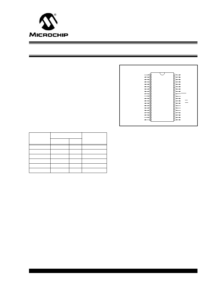
Pin Diagram
∑ TMR2: 8-bit timer/counter
∑ TMR3: 16-bit timer/counter
∑ Universal Synchronous Asynchronous Receiver
Transmitter (USART/SCI)
Special Microcontroller Features:
∑ Power-on Reset (POR), Power-up Timer (PWRT)
and Oscillator Start-up Timer (OST)
∑ Watchdog Timer (WDT) with its own on-chip RC
oscillator for reliable operation
∑ Code-protection
∑ Power saving SLEEP mode
∑ Selectable oscillator options
CMOS Technology:
∑ Low-power, high-speed CMOS EPROM/ROM
technology
∑ Fully static design
∑ Wide operating voltage range (2.5V to 6.0V)
∑ Commercial and Industrial Temperature Range
∑ Low-power consumption
- < 5 mA @ 5V, 4 MHz
- 100
µ
A typical @ 4.5V, 32 kHz
- < 1
µ
A typical standby current @ 5V
PIC17C4X
RD0/AD8
RD1/AD9
RD2/AD10
RD3/AD11
RD4/AD12
RD5/AD13
RD6/AD14
RD7/AD15
MCLR/V
PP
V
SS
RE0/ALE
RE1/OE
RE2/WR
TEST
RA0/INT
RA1/T0CKI
RA2
RA3
RA4/RX/DT
RA5/TX/CK
V
DD
RC0/AD0
RC1/AD1
RC2/AD2
RC3/AD3
RC4/AD4
RC5/AD5
RC6/AD6
RC7/AD7
V
SS
RB0/CAP1
RB1/CAP2
RB2/PWM1
RB3/PWM2
RB4/TCLK12
RB5/TCLK3
RB6
RB7
OSC1/CLKIN
OSC2/CLKOUT
1
2
3
4
5
6
7
8
9
10
11
12
13
14
15
16
17
18
19
20
40
39
38
37
36
35
34
33
32
31
30
29
28
27
26
25
24
23
22
21
PDIP, CERDIP, Windowed CERDIP
PIC17C4X
High-Performance 8-Bit CMOS EPROM/ROM Microcontroller
NOT recommended for new designs, use 17C42A.
This document was created with FrameMaker 4 0 4
PIC17C4X
DS30412C-page 2
©
1996 Microchip Technology Inc.
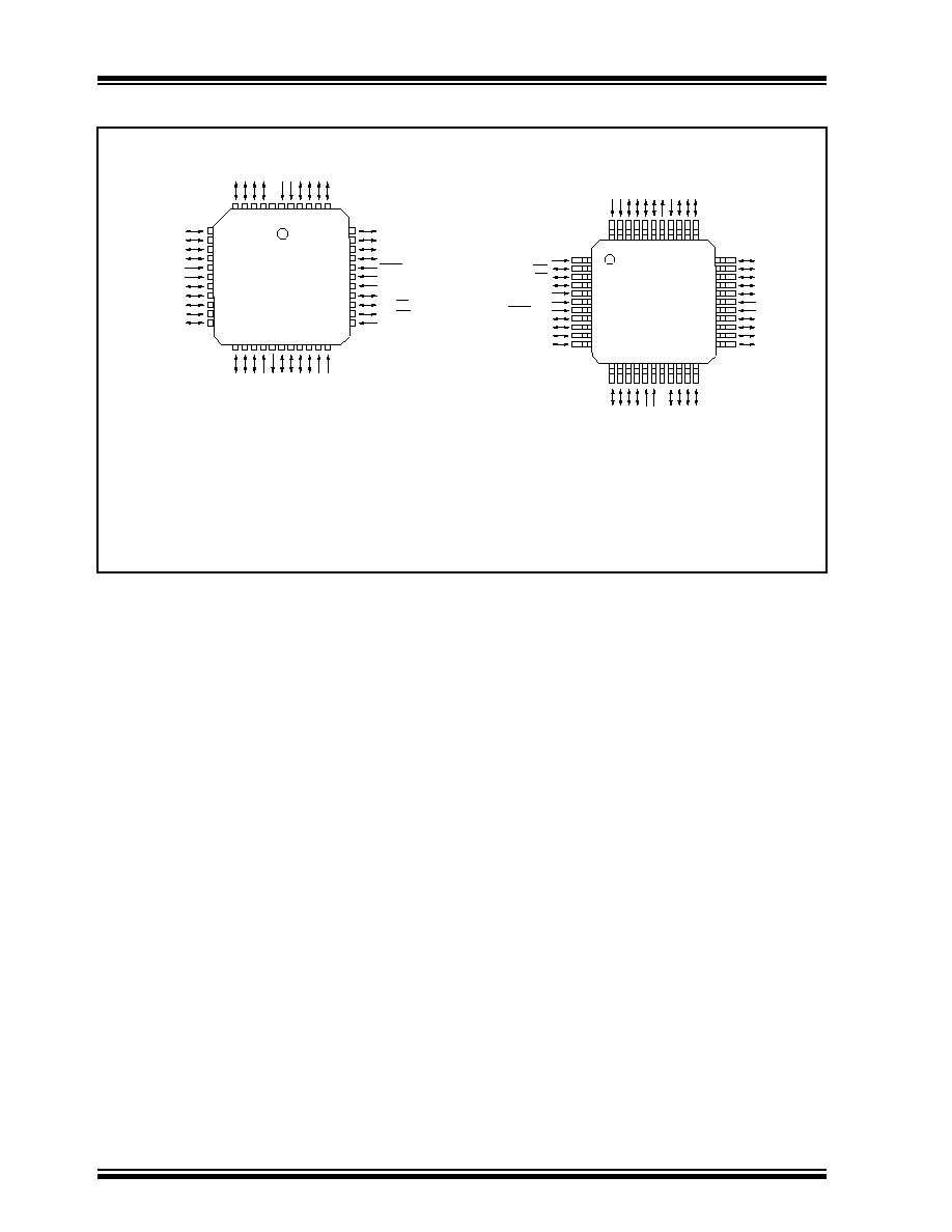
Pin Diagrams Cont.'d
RD4/AD12
RD5/AD13
RD6/AD14
RD7/AD15
MCLR/V
PP
V
SS
V
SS
RE0/ALE
RE1/OE
RE2/WR
TEST
RC4/AD4
RC5/AD5
RC6/AD6
RC7/AD7
V
SS
V
SS
RB0/CAP1
RB1/CAP2
RB2/PWM1
RB3/PWM2
RB4/TCLK12
RC3/AD3
RC2/AD2
RC1/AD1
RC0/AD0
NC
V
DD
V
DD
RD0/AD8
RD1/AD9
RD2/AD10
RD3/AD11
7
8
9
10
11
12
13
14
15
16
17
39
38
37
36
35
34
33
32
31
30
29
RA0/INT
RA1/T0CKI
RA2
RA3
RA4/RX/DT
RA5/TX/CK
OSC2/CLK
OUT
OSC1/CLKIN
RB7
RB6
RB5/TCLK3
6
5
4
3
2
1
44
43
42
41
40
28
27
26
25
24
23
22
21
20
19
18
RB4/TCLK12
RB3/PWM2
RB2/PWM1
RB1/CAP2
RB0/CAP1
V
SS
V
SS
RC7/AD7
RC6/AD6
RC5/AD5
RC4/AD4
TEST
RE2/WR
RE1/OE
RE0/ALE
V
SS
V
SS
MCLR/V
PP
RD7/AD15
RD6/AD14
RD5/AD13
RD4/AD12
RA0/INT
RA1/T0CKI
RA2
RA3
RA4/RX/DT
RA5/TX/CK
OSC2/CLK
OUT
OSC1/CLKIN
RB7
RB6
RB5/TCLK3
1
2
3
4
5
6
7
8
9
10
11
33
32
31
30
29
28
27
26
25
24
23
RC3/AD3
RC2/AD2
RC1/AD1
RC0/AD0
NC
V
DD
V
DD
RD0/AD8
RD1/AD9
RD2/AD10
RD3/AD11
44
43
42
41
40
39
38
37
36
35
34
22
21
20
19
18
17
16
15
14
13
12
PLCC
MQFP
TQFP
All devices are available in all package types, listed in Section 21.0, with the following exceptions:
∑ ROM devices are not available in Windowed CERDIP Packages
∑ TQFP is not available for the PIC17C42.
PIC17C4X
PIC17C4X
©
1996 Microchip Technology Inc.
DS30412C-page 3
PIC17C4X
Table of Contents
1.0
Overview .............................................................................................................................................................. 5
2.0
PIC17C4X Device Varieties ................................................................................................................................. 7
3.0
Architectural Overview ......................................................................................................................................... 9
4.0
Reset .................................................................................................................................................................. 15
5.0
Interrupts ............................................................................................................................................................ 21
6.0
Memory Organization ......................................................................................................................................... 29
7.0
Table Reads and Table Writes........................................................................................................................... 43
8.0
Hardware Multiplier ............................................................................................................................................ 49
9.0
I/O Ports ............................................................................................................................................................. 53
10.0
Overview of Timer Resources ............................................................................................................................ 65
11.0
Timer0 ................................................................................................................................................................ 67
12.0
Timer1, Timer2, Timer3, PWMs and Captures................................................................................................... 71
13.0
Universal Synchronous Asynchronous Receiver Transmitter (USART) Module ................................................ 83
14.0
Special Features of the CPU.............................................................................................................................. 99
15.0
Instruction Set Summary .................................................................................................................................. 107
16.0
Development Support....................................................................................................................................... 143
17.0
PIC17C42 Electrical Characteristics ................................................................................................................ 147
18.0
PIC17C42 DC and AC Characteristics............................................................................................................. 163
19.0
PIC17CR42/42A/43/R43/44 Electrical Characteristics..................................................................................... 175
20.0
PIC17CR42/42A/43/R43/44 DC and AC Characteristics ................................................................................. 193
21.0
Packaging Information...................................................................................................................................... 205
Appendix A: Modifications .......................................................................................................................................... 211
Appendix B: Compatibility........................................................................................................................................... 211
Appendix C: What's New ............................................................................................................................................ 212
Appendix D: What's Changed..................................................................................................................................... 212
Appendix E: PIC16/17 Microcontrollers ...................................................................................................................... 213
Appendix F: Errata for PIC17C42 Silicon ................................................................................................................... 223
Index ............................................................................................................................................................................ 226
PIC17C4X Product Identification System .................................................................................................................... 237
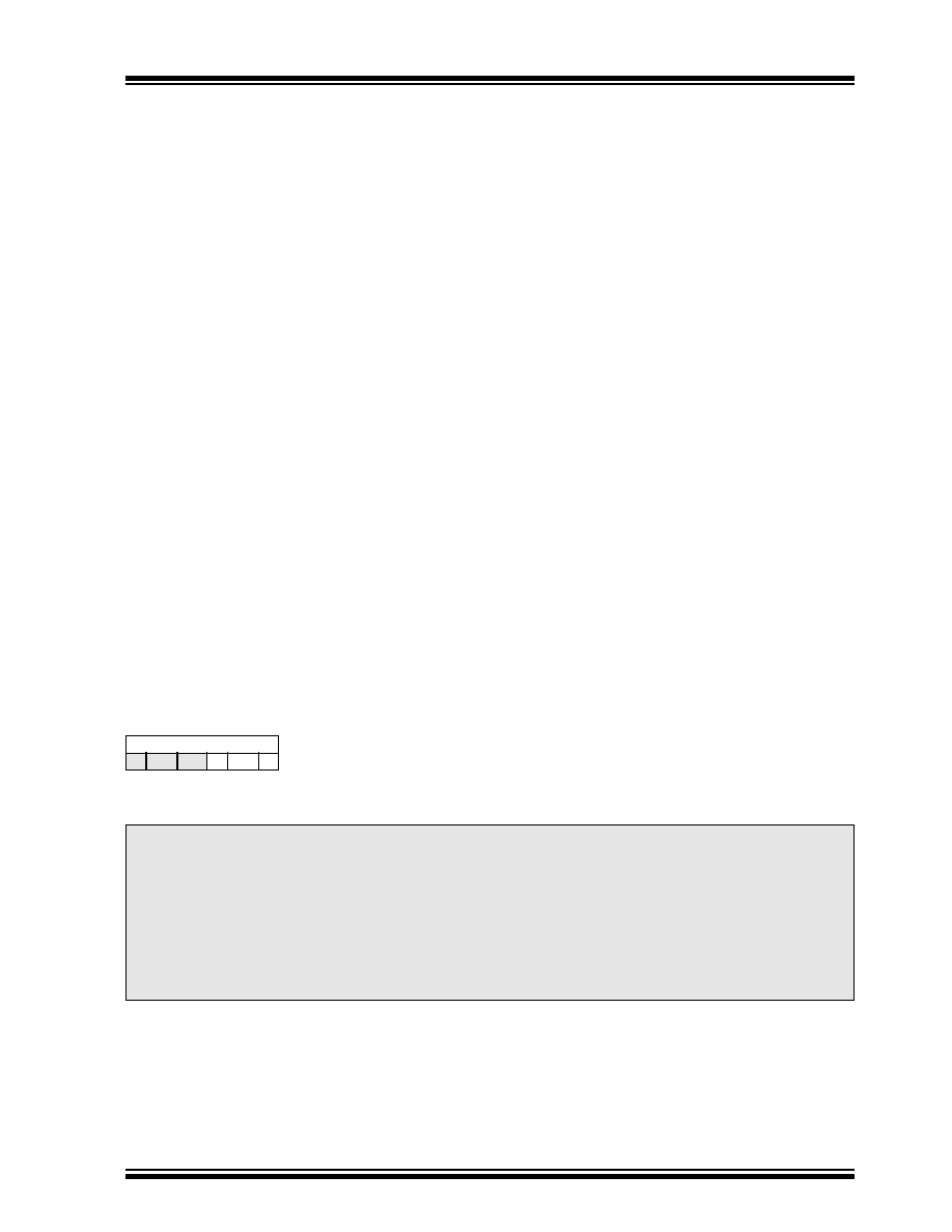
For register and module descriptions in this data sheet, device legends show which devices apply to those sections.
For example, the legend below shows that some features of only the PIC17C43, PIC17CR43, PIC17C44 are described
in this section.
Applicable Devices
42 R42 42A 43 R43 44
To Our Valued Customers
We constantly strive to improve the quality of all our products and documentation. We have spent an excep-
tional amount of time to ensure that these documents are correct. However, we realize that we may have
missed a few things. If you find any information that is missing or appears in error from the previous version of
the PIC17C4X Data Sheet (Literature Number DS30412B), please use the reader response form in the back
of this data sheet to inform us. We appreciate your assistance in making this a better document.
To assist you in the use of this document, Appendix C contains a list of new information in this data sheet,
while Appendix D contains information that has changed

PIC17C4X
DS30412C-page 4
©
1996 Microchip Technology Inc.
NOTES:

©
1996 Microchip Technology Inc.
DS30412C-page 5
PIC17C4X
1.0
OVERVIEW
This data sheet covers the PIC17C4X group of the
PIC17CXX family of microcontrollers. The following
devices are discussed in this data sheet:
∑ PIC17C42
∑ PIC17CR42
∑ PIC17C42A
∑ PIC17C43
∑ PIC17CR43
∑ PIC17C44
The PIC17CR42, PIC17C42A, PIC17C43,
PIC17CR43, and PIC17C44 devices include architec-
tural enhancements over the PIC17C42. These
enhancements will be discussed throughout this data
sheet.
The PIC17C4X devices are 40/44-Pin,
EPROM/ROM-based members of the versatile
PIC17CXX family of low-cost, high-performance,
CMOS, fully-static, 8-bit microcontrollers.
All PIC16/17 microcontrollers employ an advanced
RISC architecture. The PIC17CXX has enhanced core
features, 16-level deep stack, and multiple internal and
external interrupt sources. The separate instruction and
data buses of the Harvard architecture allow a 16-bit
wide instruction word with a separate 8-bit wide data.
The two stage instruction pipeline allows all instructions
to execute in a single cycle, except for program
branches (which require two cycles). A total of 55
instructions (reduced instruction set) are available in
the PIC17C42 and 58 instructions in all the other
devices. Additionally, a large register set gives some of
the architectural innovations used to achieve a very
high performance. For mathematical intensive applica-
tions all devices, except the PIC17C42, have a single
cycle 8 x 8 Hardware Multiplier.
PIC17CXX microcontrollers typically achieve a 2:1
code compression and a 4:1 speed improvement over
other 8-bit microcontrollers in their class.
PIC17C4X devices have up to 454 bytes of RAM and
33 I/O pins. In addition, the PIC17C4X adds several
peripheral features useful in many high performance
applications including:
∑ Four timer/counters
∑ Two capture inputs
∑ Two PWM outputs
∑ A Universal Synchronous Asynchronous Receiver
Transmitter (USART)
These special features reduce external components,
thus reducing cost, enhancing system reliability and
reducing power consumption. There are four oscillator
options, of which the single pin RC oscillator provides a
low-cost solution, the LF oscillator is for low frequency
crystals and minimizes power consumption, XT is a
standard crystal, and the EC is for external clock input.
The SLEEP (power-down) mode offers additional
power saving. The user can wake-up the chip from
SLEEP through several external and internal interrupts
and device resets.
There are four configuration options for the device oper-
ational modes:
∑ Microprocessor
∑ Microcontroller
∑ Extended microcontroller
∑ Protected microcontroller
The microprocessor and extended microcontroller
modes allow up to 64K-words of external program
memory.
A highly reliable Watchdog Timer with its own on-chip
RC oscillator provides protection against software mal-
function.
Table 1-1 lists the features of the PIC17C4X devices.
A UV-erasable CERDIP-packaged version is ideal for
code development while the cost-effective One-Time
Programmable (OTP) version is suitable for production
in any volume.
The PIC17C4X fits perfectly in applications ranging
from precise motor control and industrial process con-
trol to automotive, instrumentation, and telecom appli-
cations. Other applications that require extremely fast
execution of complex software programs or the flexibil-
ity of programming the software code as one of the last
steps of the manufacturing process would also be well
suited. The EPROM technology makes customization
of application programs (with unique security codes,
combinations, model numbers, parameter storage,
etc.) fast and convenient. Small footprint package
options make the PIC17C4X ideal for applications with
space limitations that require high performance. High
speed execution, powerful peripheral features, flexible
I/O, and low power consumption all at low cost make
the PIC17C4X ideal for a wide range of embedded con-
trol applications.
1.1
Family and Upward Compatibility
Those users familiar with the PIC16C5X and
PIC16CXX families of microcontrollers will see the
architectural enhancements that have been imple-
mented. These enhancements allow the device to be
more efficient in software and hardware requirements.
Please refer to Appendix A for a detailed list of
enhancements and modifications. Code written for
PIC16C5X or PIC16CXX can be easily ported to
PIC17CXX family of devices (Appendix B).
1.2
Development Support
The PIC17CXX family is supported by a full-featured
macro assembler, a software simulator, an in-circuit
emulator, a universal programmer, a "C" compiler, and
fuzzy logic support tools.
This document was created with FrameMaker 4 0 4