
©
2002 Microchip Technology Inc.
DS21453B-page 1
TC652/TC653
Features
∑ Integrated Temperature Sensing and Multi-speed
Fan Control
∑ FanSenseTM Fan Fault Detect Circuitry
∑ Built-in Over-Temperature Alert (T
OVER
)
∑ Temperature Proportional Fan Speed Control for
Acoustic Noise Reduction and Longer Fan Life
∑ Pulse Width Modulation Output Drive for Cost
and Power Savings
∑ Solid-State Temperature Sensing
∑ ±1∞C (Typical) Accuracy from 25∞C to +70∞C
∑ 2.8V ≠ 5.5V Operating Range
∑ TC653 includes Auto Fan Shutdown
∑ Low Operating Current: 50
µ
A (Typical)
Applications
∑ Thermal Protection For Personal Computers
∑ Digital Set-Top Boxes
∑ Notebook Computers
∑ Data Communications
∑ Power Supplies
∑ Projectors
Related Literature
∑ Application Note: AN771
Device Selection Table
The "X" denotes a suffix for temperature threshold settings.
Contact factory for other temperature ranges.
Package Type
General Description
The TC652/TC653 are integrated temperature sensors
and
brushless
DC
fan
speed
controllers
with
FanSense
TM
technology. The TC652/TC653 measure
their junction temperature and control the speed of the
fan based on that temperature, making them especially
suited for applications in modern electronic equipment.
The FanSense
TM
Fan Fault detect circuitry eliminates
the need for a more expensive 3-wire fan.
Temperature data is converted from the on-chip
thermal sensing element
and
translated
into
a
fractional fan speed from 40% to 100%. A temperature
selection guide in the data sheet is used to choose the
low and high temperature limits to control the fan. The
TC652/TC653 also include a single trip point over
temperature alert (T
OVER
) that eliminates the need for
additional temperature sensors. In addition, the TC653
includes an auto fan shutdown function for additional
power savings.
The TC652/TC653 are easy to use, require no software
overhead and are therefore the ideal choice for
implementing thermal management in a variety of
systems.
Part Number
Package
Temperature Range
TC652XXVUA
8-Pin MSOP
-40
∞
C to +125
∞
C
TC653XXVUA
8-Pin MSOP
-40
∞
C to +125
∞
C
X
Temperature
A
25
B
30
C
35
D
40
E
45
F
50
G
55
1
8
2
7
3
6
4
5
FAULT
V
DD
MSOP
GND
PWM
T
OVER
SENSE
GND
TC652
TC653
SHDN
Integrated Temperature Sensor & Brushless DC Fan
Controller with FanSenseTM Detect & Over-Temperature

TC652/TC653
DS21453B-page 2
©
2002 Microchip Technology Inc.
Typical Application Diagram
1
8
2
7
3
6
4
5
FAULT
V
DD
PWM
GND
T
OVER
SENSE
R
SENSE
FanSenseTM
GND
GND
+5V V
DD
+12V
TC652
TC653
SHDN
2
1k
0.01µF
C
SENSE
µController
DC Fan
300mA
Max.
SHDN Control
Over-Temp
Alert
Fan Fault Alert

©
2002 Microchip Technology Inc.
DS21453B-page 3
TC652/TC653
1.0
ELECTRICAL
CHARACTERISTICS
Absolute Maximum Ratings*
Input Voltage (V
DD
to GND) ................................... +6V
Output Voltage (OUT to GND) ................................. 6V
Voltage On Any Pin ....... (GND ≠ 0.3V) to (V
DD
+ 0.3V)
Package Thermal Resistance (
JA
)
........... 250∞C/W
Operating Temperature Range ......... -40∞C to +125∞C
Storage Temperature ......................... -65∞C to +150∞C
*Stresses above those listed under "Absolute Maximum Rat-
ings" may cause permanent damage to the device. These are
stress ratings only and functional operation of the device at
these or any other conditions above those indicated in the
operation sections of the specifications is not implied. Expo-
sure to Absolute Maximum Rating conditions for extended
periods may affect device reliability.
TC652/TC653 ELECTRICAL SPECIFICATIONS
Electrical Characteristics: V
DD
= 2.8V to 5.5V, SHDN = V
DD
, T
A
= -40
∞
C to 125
∞
C unless otherwise specified.
Symbol
Parameter
Min
Typ.
Max
Units
Test Conditions
V
DD
Supply Voltage
2.8
--
5.5
V
I
DD
Supply Current
--
50
90
µ
A
PWM, FAULT, T
OVER
are
open
SHDN Input
V
IH
SHDN Input High Threshold
65
--
--
%V
DD
V
IL
SHDN Input Low Threshold
--
--
15
%V
DD
PWM Output
V
OL
PWM Output Low Voltage
--
--
0.3
V
I
SINK
= 1mA
V
OH
PWM Output High Voltage
V
DD
≠ 0.5
--
--
V
I
SOURCE
= 5mA
t
R
PWM Rise Time
--
10
--
µ
sec
I
OH
= 5mA, 1nF from
PWM to GND
t
F
PWM Fall Time
--
10
--
µ
sec
I
OL
= 1mA, 1nF from
PWM to GND
f
OUT
PWM Frequency
10
15
--
Hz
t
STARTUP
Start-up Time
--
32/f
OUT
--
sec
V
DD
Rises from GND,
or SHDN Released
V
TH (SENSE)
Sense Input
--
70
--
mV
Sense Input Threshold
Voltage with Repect to
Ground
Temperature Accuracy
T
H ACC
High Temperature Accuracy
T
H
- 3
T
H
T
H
+ 3
∞
C
Note 1
(T
H ≠
T
L
)
ACC
Temp. Range Accuracy
-1.0
--
+1.0
∞
C
(T
H
≠ T
L
)
20
∞
C
-2.5
--
+2.5
∞
C
(T
H
≠ T
L
)
20
∞
C
T
HYST
Auto-shutdown Hysteresis
--
(T
H
≠ T
L
)/5
--
∞
C
TC653 Only
FAULT Output
V
HIGH
FAULT Output High Voltage
V
DD
≠ 0.5
--
--
V
I
SOURCE
= 1.2mA
V
LOW
FAULT Output Low Voltage
--
--
0.4
V
I
SINK
= 2.5mA
tmp
Missing Pulse Detector
Time-out
--
--
32/f
OUT
Sec
T
OVER
Output
V
HIGH
T
OVER
Output High Voltage
V
DD
≠ 0.5
--
--
V
I
SOURCE
= 1.2mA
V
LOW
T
OVER
Output Low Voltage
--
--
0.4
V
I
SINK
= 2.5mA
T
OVER ACC
Absolute Accuracy
--
T
H
+ 10
--
∞C
At Trip Point
T
OVER HYST
Trip Point Hysteresis
--
5
--
∞C
Note
1:
Transition from 90% to 100% Duty Cycle.
TC652/TC653
DS21453B-page 4
©
2002 Microchip Technology Inc.
2.0
PIN DESCRIPTIONS
The descriptions of the pins are listed in Table 2-1.
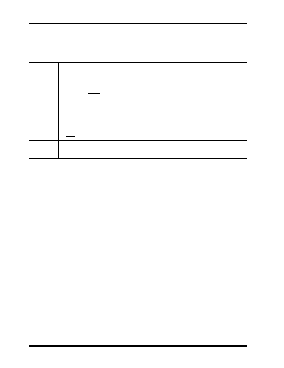
TABLE 2-1:
PIN FUNCTION TABLE
Pin No.
(8-Pin MSOP)
Symbol
Description
1
V
DD
Power Supply Input. May be independent of fan power supply.
2
FAULT
Fan Fault Alert, Active-Low Output. FAULT goes low to indicate a fan FAULT condition.
When FAULT occurs, the device is latched in Shutdown mode with PWM low. Toggling
the SHDN pin or cycling the V
DD
will release the part and fan from shutdown. FAULT will
unconditionally remain high during shutdown.
3
SHDN
Fan Shutdown, Active-Low Input. During Shutdown mode the chip still monitors
temperature and T
OVER
is low if temperature rises above factory set point.
4
GND
Ground return for all TC652/TC653 functions.
5
SENSE
Detect Fan Pulses Input. Pulses are detected at this pin as fan rotation chops the current
through the sense resistor, R
SENSE
. The absence of pulses indicates a Fan Fault.
6
T
OVER
Over-Temperature Alert, Active-Low Output.
7
GND
Ground.
8
PWM
PWM Fan Drive Output. Pulse width modulated rail-to-rail logic output. Nominal
Frequency is 15Hz.
©
2002 Microchip Technology Inc.
DS21453B-page 5
TC652/TC653
3.0
DETAILED DESCRIPTION
The TC652/TC653 acquire and convert their junction
temperature (T
J
) information from an on-chip solid
state sensor with a typical accuracy of ±1∞C. The
temperature data is digitally stored in an internal
register. The register is compared with pre-defined
threshold values. The six threshold values are equally
distributed over a pre-defined range of temperatures
(See Table 3-1 and Table 3-2). The TC652/TC653
control the speed of a DC brushless fan using a
fractional speed control scheme. The output stage
requires only a 2N2222-type small-signal BJT for fans
up to 300mA. For larger current fans (up to 1 Amp) a
logic-level N-channel MOSFET may be used. In
addition to controlling the speed of the fan, the TC652/
TC653 include an on-chip over-temperature alarm
(T
OVER
) that gives a low-true signal when the
temperature of the chip exceeds T
H
by 10∞C. This
feature eliminates the need for a separate temperature
sensor for over-temperature monitoring.
In normal fan operation, a pulse-train is present at
SENSE, Pin 5. A Missing Pulse Detector monitors this
pin during fan operation (FanSense
TM
technology). A
stalled, open, or unconnected fan causes the TC652/
TC653 to trigger its Start-up Timer once. If the FAULT
persists, the FAULT output goes low, and the device is
latched in its Shutdown mode. To release the fan from
shutdown, toggle the SHDN or V
DD
pin.
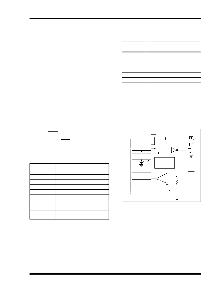
TABLE 3-1:
TEMPERATURE RANGE
DEFINITION FOR TC652
(MINIMUM-SPEED MODE)
TABLE 3-2:
TEMPERATURE RANGE
DEFINITION FOR TC653
(AUTO-SHUTDOWN MODE)
FIGURE 3-1:
FUNCTIONAL BLOCK
DIAGRAM
3.1
PWM Output
The PWM pin is designed to drive a low cost transistor
or MOSFET as the low side power switching element in
the
system.
This
output
has
an
asymmetric
complementary drive and is optimized for driving NPN
transistors or N-channel MOSFETs. Since the system
relies on PWM rather than linear power control, the
dissipation in the power switch is kept to a minimum.
Generally,
very
small
devices
(TO-92
or
SOT
packages) will suffice. The frequency of the PWM is
about 15Hz. The PWM is also the time base for the
Start-up Timer (see paragraphs below). The PWM duty
cycle has a range of 40% to 100% for the TC652 and
50% to 100% for the TC653.
Temperature
(T = T
J
)
PWM Duty Cycle
T < T
L
40%
T
L
< = T < T
1
50%
T
1
< = T < T
2
60%
T
2
< = T <T
3
70%
T
3
< = T < T
4
80%
T
4
< = T < T
H
90%
T
H
< = T < T
OV
100%
T
OV
< = T
100% with Over-Temp Alert
(T
OVER
= L)
Temperature
(T = T
J
)
PWM Duty Cycle
T < T
L
"OFF"
T
L
< = T < T
1
50%
T
1
< = T < T
2
60%
T
2
< =T < T
3
70%
T
3
< =T < T
4
80%
T
4
< = T < T
H
90%
T
H
< = T < T
OV
100%
T
OV
< = T
100% with Over-Temp Alert
(T
OVER
= L)
Note: The temperature regions defined by the six tempera-
ture thresholds are pre-defined in the TC650/651 by means
of trimming. Once a T
L
and T
H
are programmed, the T
1
- T
4
thresholds are automatically equally spaced between T
L
and
T
H
.
Temp Sensor
Fan Detect
Logic
Duty Cycle
Logic
Control
AD Converter
Oscillator
Temperature
Set Point and
Trim Range
SHDN
T
OVER
PWM
FAULT
90mV
V
DD
V+
CMPTR
+
-
20k
-
-