MSP 3438G
PRELIMINARY DATA SHEET
2
MICRONAS INTERMETALL
Contents
Page
Section
Title
5
1.
Introduction
6
1.1.
Features of the MSP 34x8G Family
6
1.2.
MSP 34x8G Version List
7
1.3.
MSP 34x8G Versions and their Application Fields
8
2.
Functional Description
9
2.1.
Architecture of the MSP 34x8G Family
9
2.2.
Sound IF Processing
9
2.2.1.
Analog Sound IF Input
9
2.2.2.
Demodulator: Standards and Features
10
2.2.3.
Preprocessing of Demodulator Signals
10
2.2.4.
Automatic Sound Select
10
2.3.
Preprocessing for SCART and I
2
S Input Signals
12
2.4.
Source Selection and Output Channel Matrix
12
2.4.1.
Mixing Unit
12
2.5.
Audio Baseband Processing
12
2.5.1.
Automatic Volume Correction (AVC)
12
2.5.2.
Loudspeaker and Aux Outputs
12
2.5.3.
Quasi-Peak Detector
13
2.6.
SCART Signal Routing
13
2.6.1.
SCART DSP In and SCART Out Select
13
2.6.2.
Stand-by Mode
13
2.7.
I
2
S Bus Interfaces
13
2.7.1.
Synchronous I2S-Interface(s)
13
2.7.2.
Asynchronous I2S-Interface
14
2.8.
ADR Bus Interface
14
2.9.
Digital Control I/O Pins and Status Change Indication
14
2.10.
Preemphasis
14
2.11.
Clock PLL Oscillator and Crystal Specifications
15
3.
Control Interface
15
3.1.
I
2
C Bus Interface
15
3.1.1.
Device and Subaddresses
16
3.1.2.
Protocol Description
17
3.1.3.
Proposals for General MSP 34x8G I
2
C Telegrams
17
3.1.3.1.
Symbols
17
3.1.3.2.
Write Telegrams
17
3.1.3.3.
Read Telegrams
17
3.1.3.4.
Examples
17
3.2.
Start-Up Sequence: Power-Up and I
2
C Controlling
17
3.3.
MSP 34x8G Programming Interface
17
3.3.1.
User Registers Overview
20
3.3.2.
Description of User Registers
21
3.3.2.1.
STANDARD SELECT Register
21
3.3.2.2.
STANDARD RESULT Register
22
3.3.2.3.
Write Registers on I
2
C Subaddress 10
hex
24
3.3.2.4.
Read Registers on I
2
C Subaddress 11
hex

Contents, continued
Page
Section
Title
PRELIMINARY DATA SHEET
MSP 3438G
MICRONAS INTERMETALL
3
25
3.3.2.5.
Write Registers on I
2
C Subaddress 12
hex
31
3.3.2.6.
Read Registers on I
2
C Subaddress 13
hex
33
3.4.
Programming Tips
33
3.5.
Examples of Minimum Initialization Codes
33
3.5.1.
B/G-FM (A2 or NICAM)
33
3.5.2.
BTSC-Stereo
33
3.5.3.
BTSC-SAP with SAP at Loudspeaker Channel
34
3.5.4.
FM-Stereo Radio
34
3.5.5.
Automatic Standard Detection
34
3.5.6.
Software Flow for Interrupt driven STATUS Check
35
4.
Specifications
35
4.1.
Outline Dimensions
37
4.2.
Pin Connections and Short Descriptions
40
4.3.
Pin Descriptions
43
4.4.
Pin Configurations
47
4.5.
Pin Circuits
49
4.6.
Electrical Characteristics
49
4.6.1.
Absolute Maximum Ratings
50
4.6.2.
Recommended Operating Conditions (T
A
= 0 to 70
°
C)
50
4.6.2.1.
General Recommended Operating Conditions
50
4.6.2.2.
Analog Input and Output Recommendations
51
4.6.2.3.
Recommendations for Analog Sound IF Input Signal
52
4.6.2.4.
Crystal Recommendations
53
4.6.3.
Characteristics
53
4.6.3.1.
General Characteristics
54
4.6.3.2.
Digital Inputs, Digital Outputs
55
4.6.3.3.
Reset Input and Power-Up
56
4.6.3.4.
I
2
C-Bus Characteristics
57
4.6.3.5.
I
2
S-Bus Characteristics
59
4.6.3.6.
Analog Baseband Inputs and Outputs, AGNDC
61
4.6.3.7.
Sound IF Inputs
61
4.6.3.8.
Power Supply Rejection
62
4.6.3.9.
Analog Performance
65
4.6.3.10.
Sound Standard Dependent Characteristics
68
5.
Appendix A: Overview of TV-Sound Standards
68
5.1.
NICAM 728
69
5.2.
A2-Systems
70
5.3.
BTSC-Sound System
70
5.4.
Japanese FM Stereo System (EIA-J)
71
5.5.
FM Satellite Sound
71
5.6.
FM-Stereo Radio

MSP 3438G
PRELIMINARY DATA SHEET
4
MICRONAS INTERMETALL
Contents, continued
Page
Section
Title
72
6.
Appendix B: Manual Mode
72
6.1.
Demodulator Write and Read Registers for Manual Mode
73
6.2.
DSP Write and Read Registers for Manual Mode
74
6.3.
Manual Mode: Description of Demodulator Write Registers
74
6.3.1.
Automatic Switching between NICAM and Analog Sound
74
6.3.1.1.
Function in Automatic Sound Select Mode
74
6.3.1.2.
Function in Manual Mode
75
6.3.2.
A2 Threshold
75
6.3.3.
Carrier-Mute Threshold
76
6.3.4.
DCO-Registers
77
6.4.
Manual Mode: Description of Demodulator Read Registers
77
6.4.1.
NICAM Mode Control/Additional Data Bits Register
77
6.4.2.
Additional Data Bits Register
77
6.4.3.
CIB Bits Register
78
6.4.4.
NICAM Error Rate Register
78
6.4.5.
Automatic Search Function for FM-Carrier Detection in Satellite Mode
79
6.5.
Manual Mode: Description of DSP Write Registers
79
6.5.1.
Additional Channel Matrix Modes
79
6.5.2.
FM Fixed Deemphasis
79
6.5.3.
FM Adaptive Deemphasis
79
6.5.4.
NICAM Deemphasis
80
6.5.5.
Identification Mode for A2 Stereo Systems
80
6.6.
Manual Mode: Description of DSP Read Registers
80
6.6.1.
Stereo Detection Registerfor A2 Stereo Systems
80
6.6.2.
DC Level Register
80
6.7.
Demodulator Source Channels in Manual Mode
80
6.7.1.
Terrestrial Sound Standards
80
6.7.2.
SAT Sound Standards
82
6.8.
Exclusions of Audio Baseband Features
82
6.9.
Phase Relationship of Analog Outputs
83
7.
Appendix C: Application Circuit
84
8.
Data Sheet History
PRELIMINARY DATA SHEET
MSP 3438G
MICRONAS INTERMETALL
5
Multistandard Sound Processor Family
The hardware and software description in this docu-
ment is valid only for the MSP 3438G version A1.
All new versions of the MSP 3438G and all other men-
tioned members of the MSP 34x8G family will be real-
ized within the MSP 44x8G family with an extended
feature set. Please refer to the appropriate data sheet.
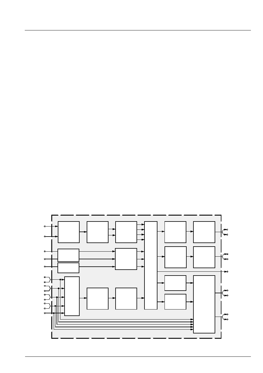
1. Introduction
The MSP 34x8G family of Multistandard Sound Pro-
cessors covers the sound processing of all analog TV-
Standards worldwide, as well as the NICAM digital
sound standards. The full TV sound processing, start-
ing with analog sound IF signal-in, down to processed
analog AF-out, is performed on a single chip. Figure
11 shows a simplified functional block diagram of the
MSP 34x8G.
The high-quality A/D and D/A converters offer the full
audio bandwidth of 20 kHz and the backend DSP pro-
cessing is performed at a 48 kHz sample rate.
The MSP 34x8G has been designed for the usage in
hybrid set-top boxes and multimedia applications. Its
asynchronous I
2
S slave interface allows the reception
of digital stereo signals with arbitrary sample rates
ranging from 5 to 50 kHz. Synchronization is per-
formed by means of an adaptive sample rate con-
verter.
The processed standards include the multichannel
television sound signal (MTS) which conforms to the
recommendations of the BTSC, as well as the Japa-
nese FM-FM multiplex standard (EIA-J). For these
standards, optimum stereo separation is achieved
without any adjustment. In addition, the MSP 34x8G is
also able to receive FM stereo radio and, in conjunc-
tion with the DRP 3510, ASTRA Digital Radio (ADR).
The DBX noise reduction is performed alignment-free.
The MSP 34x8G versions are pin and software com-
patible to other MSP families. Standard selection
requires only a single I
2
C transmission.
Several built-in automatic functions detect the actual
sound standard (Automatic Standard Detection) or
evaluate pilot levels and identification signals. Auto-
matic switching between mono/stereo/bilingual is per-
formed by the Automatic Sound Selection.
A status change indication signal makes polling of sta-
tus information unnecessary.
The ICs are produced in submicron CMOS technology
and are available in the following packages: PQFP80,
PLQFP64, PLCC68, and PSDIP64.
Fig. 11: Simplified functional block diagram of the MSP 34x8G
So
u
r
ce S
e
l
ect
Loud-
SCART1
SCART2
SCART1
SCART2
SCART4
SCART3
MONO
De-
modulator
Aux
Headphone
I
2
S
Sound
Processing
speaker
Sound
Processing
DAC
DAC
ADC
Loud-
DAC
DAC
ADC
SCART
DSP
Input
Select
Pre-
processing
SCART
Output
Select
Prescale
Prescale
I
2
S1
I
2
S2
Sound IF1
Sound IF2
speaker
/Modulator
I
2
S3
synchron.
I
2
S
asynchron.
I
2
S