 | –≠–ª–µ–∫—Ç—Ä–æ–Ω–Ω—ã–π –∫–æ–º–ø–æ–Ω–µ–Ω—Ç: 53257 | –°–∫–∞—á–∞—Ç—å:  PDF PDF  ZIP ZIP |

Micropac Industries cannot assume any responsibility for any circuits shown or represent that they are free from patent infringement.
Micropac reserves the right to make changes at any time in order to improve design and to supply the best product possible.
MICROPAC INDUSTRIES, INC. HYBRID MICROELECTRONICS PRODUCTS DIVISION
∑ 905 E. Walnut St., Garland, TX 75040 ∑ (972) 272-3571 ∑ Fax (972) 494-2281
www.micropac.com
E-MAIL:
hybridsales@micropac.com
05/16/01
PRELIMINARY DATA SHEET
53257
RADIATION TOLERANT
120VDC ≠ 2A SOLID STATE RELAY
Mii
HYBRID MICROELECTRONICS
PRODUCTS DIVISION
Features:
∑ Design for 100 krad(Si) Total Dose
∑ Hermetically Sealed in Surface Mount Package
∑ Low
On-resistance
∑ 2A Continuous Output Current
∑ Operation over Full Military Temperature
Range -55∞C to +125∞C
∑ Optically
Coupled
∑ Input / Output Isolation Tested to 1000 VDC
∑ Shock and Vibration Resistance
Applications:
∑ Satellite/Space
Systems
∑ Military/High Reliability Systems
∑ Power
Distribution/Switching
∑ Solenoid
Driver
∑ Stepper Motor Driver
∑ Switching
Heaters
DESCRIPTION
The 53257 is a radiation tolerant, DC solid-state relay (SSR) designed for military and space applications. This light
weight device is resistant to damage from severe shock and vibration, and is immune to contact related problems
inherent in electro-mechanical relays. The 53257 SSR is enclosed in a hermetic metal package to ensure reliability
in harsh environments. Effective isolation of 1000 VDC between control and load circuits is achieved through the
use of optical coupling.
Functionally, the device operates as a single-pole single-throw, normally open (1 Form A) DC solid-state relay. The
53257 SSR is actuated by an input current of 5 to 15 mA, which can be supplied from a standard TTL device.
Output is provided by a power MOSFET exhibiting low R
DS(ON)
and capable of carrying a continuous current of 2
amperes. This device is designed to function with minimal degradation after exposure to 100 krad(Si) total dose.
This device is available in a variety of quality of levels from COTS to class K including any custom screening
requirements. The basic data sheet part is environmentally screened to H level in accordance with Table C-IX of
MIL-PRF-38534.
ABSOLUTE MAXIMUM RATINGS
Output Voltage ..................................................................................................................................................... 150 VDC
Continuous Output current ............................................................................................................................................2 A
Storage Temperature Range ..................................................................................................................-65∞C to +150∞C
Operating Junction Temperature...........................................................................................................................+150∞C
Lead Solder Temperature, for 10 seconds .............................................................................................................300∞C
Continuous Input Current .........................................................................................................................................20 mA
Peak Input Current
(1)
............................................................................................................................................. 100 mA
Reverse Input Voltage............................................................................................................................................. 6 VDC
WEIGHT: ........................................................................................................................................3.7 grams (typical)
Micropac Industries cannot assume any responsibility for any circuits shown or represent that they are free from patent infringement.
Micropac reserves the right to make changes at any time in order to improve design and to supply the best product possible.
MICROPAC INDUSTRIES, INC. HYBRID MICROELECTRONICS PRODUCTS DIVISION
∑ 905 E. Walnut St., Garland, TX 75040 ∑ (972) 272-3571 ∑ Fax (972) 494-2281
www.micropac.com
E-MAIL:
hybridsales@micropac.com
05/16/01
Preliminary Data Sheet
53257
Radiation Tolerant 120VDC - 2A Solid State Relay
_________________________________________________________________
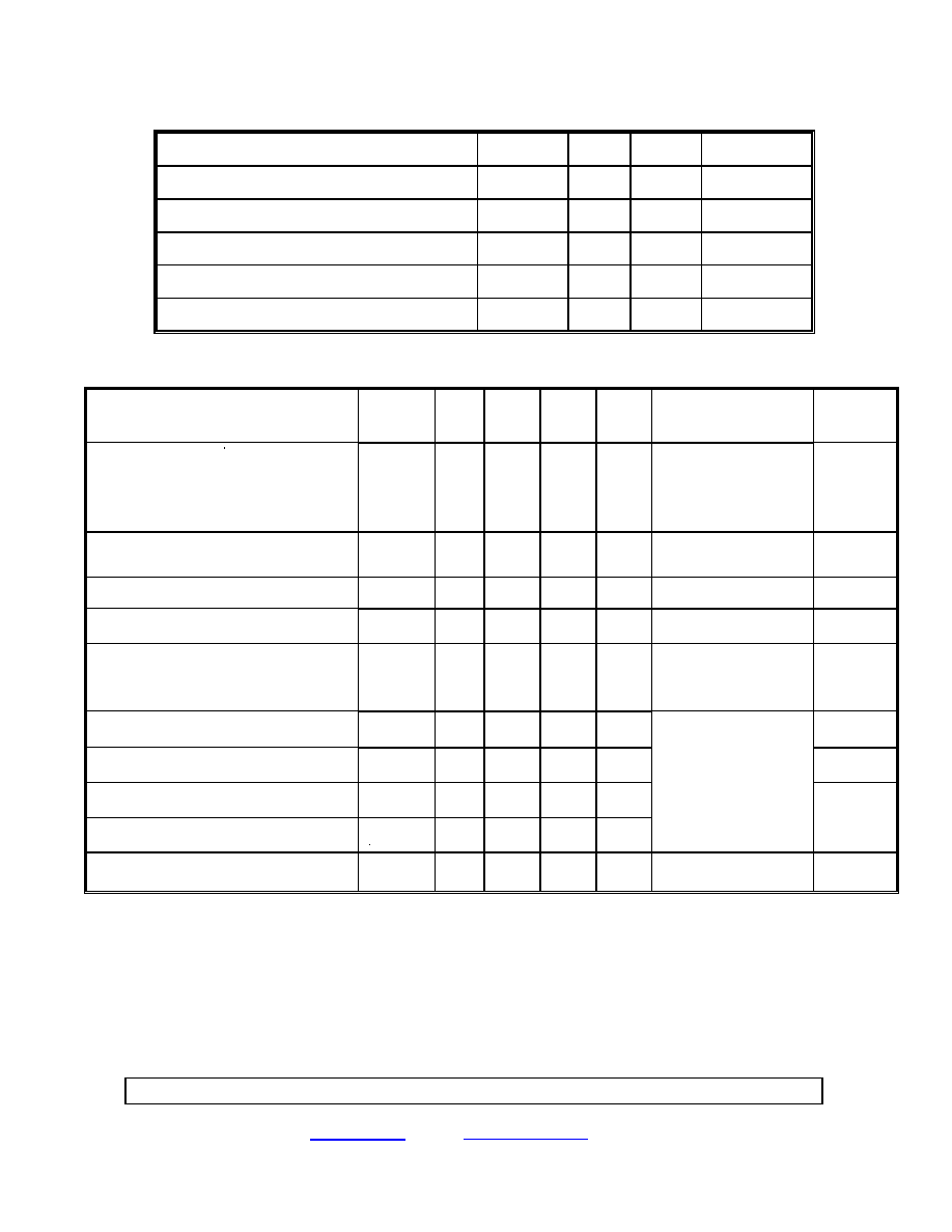
RECOMMENDED OPERATING CONDITIONS:
Parameter
Symbol
Min.
Max.
Units
Output Voltage
(5)
V
O (OFF)
120
VDC
Continuous Output Current
I
O (ON)
2
A
Input Current (on)
I
F (ON)
5
15
mA
Input Voltage (off)
V
F (OFF)
0
1
VDC
Operating Case Temperature
T
C
-55
125
∞C
ELECTRICAL SPECIFICATIONS (Pre-Irradiation)
T
C
= -55∞C to +125∞C unless otherwise specified
Parameter
Symbol
Min.
Typ.*
Max.
Unit
s
Test Conditions
Notes
Output On-Resistance
R
(ON)
.110
.220
I
F
= 15 mA
Io = 2 A
Pulse width = 10 ms
Duty cycle
10%
Output Leakage Current
I
O (OFF)
250
µA
V
F
= 1 VDC
V
O
= 150 VDC
Input Forward Voltage
V
F
4.20
VDC
I
F
= 15 mA
Input Reverse Breakdown Voltage
V
R
6
40
VDC
I
R
= 10
µA
Input-Output Leakage Current
I
I-O
1
µA
RH
45%, t = 5 s
V
I-O
= 1000 VDC
T
C
= 25∞C
2, 3
Turn-On Time
t
ON
8
ms
Figure 3
Turn-Off time
t
OFF
2
ms
Figure 3
Rise Time
t
R
6
ms
Fall Time
t
F
1
ms
I
F
= 15 mA
Io = 2 A
Pulse width = 10 ms
Duty cycle
10%
4,
Figure 3
Thermal Resistance (junction-case)
JC
5.5
∞C/W
* All typical values are at T
C
= 25∞C
Notes:
1. Non-repetitive, pulse width
100 µs, T
C
= 25∞C.
2. Input pins shorted together and output pins shorted together.
3. Input-output potential applied momentarily, not a steady state operating condition.
4. Rise time is measured from 10% to 90% of load current (90% to 10% of V
O
). Fall time is measured from 90% to
10% of load current (10% to 90% of V
O
).
5. The user should apply the appropriate transient suppression technique to the output terminals of the relay when
the loads are inductive enough to generate voltage spikes.
Micropac Industries cannot assume any responsibility for any circuits shown or represent that they are free from patent infringement.
Micropac reserves the right to make changes at any time in order to improve design and to supply the best product possible.
MICROPAC INDUSTRIES, INC. HYBRID MICROELECTRONICS PRODUCTS DIVISION
∑ 905 E. Walnut St., Garland, TX 75040 ∑ (972) 272-3571 ∑ Fax (972) 494-2281
www.micropac.com
E-MAIL:
hybridsales@micropac.com
05/16/01
Preliminary Data Sheet
53257
Radiation Tolerant 120VDC - 2A Solid State Relay
_________________________________________________________________
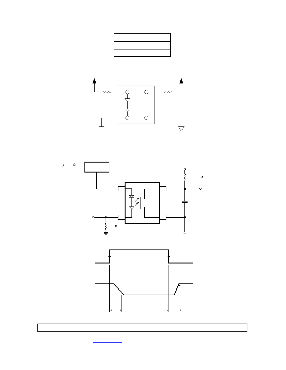
INPUT
OUTPUT
ON
ON
OFF
OFF
Figure 1. Truth Table
R
LOAD
+V
C
3
2
1
-V
C
4
+DC SUPPLY
OUTPUT GND
TOP VIEW
R
S
Figure 2. Terminal Connections
PULSE
GENERATOR
50%
MONITOR
90%
ON
10%
OFF
MONITOR
2
50%
3
(INCLUDES PROBE AND
FIXTURE CAPACITANCE)
1
4
R = 20
V = 40 V
L
VO
CL
LOAD
F
I
F
I
O
V
t
Z = 50
O
R
t = t = 10ns
F
t
(100mV/mA)
= 25 pF
100
F
igure 3. Switching Waveforms and Test Circuits

Micropac Industries cannot assume any responsibility for any circuits shown or represent that they are free from patent infringement.
Micropac reserves the right to make changes at any time in order to improve design and to supply the best product possible.
MICROPAC INDUSTRIES, INC. HYBRID MICROELECTRONICS PRODUCTS DIVISION
∑ 905 E. Walnut St., Garland, TX 75040 ∑ (972) 272-3571 ∑ Fax (972) 494-2281
www.micropac.com
E-MAIL:
hybridsales@micropac.com
05/16/01
Preliminary Data Sheet
53257
Radiation Tolerant 120VDC - 2A Solid State Relay
_________________________________________________________________
CASE OUTLINE
.500
.175
1.060
±.030
.500
.025
±.002 DIA
(4 PLCS)
.060
(TYP)
.300
1
2
3
4