MICROPAC INDUSTRIES, INC.
OPTOELECTRONIC PRODUCTS DIVISION ∑ 725 E.Walnut Str., Garland, TX 75040 ∑ (972)272-3571 ∑ Fax (972)487-6918
www.micropac.com
E-MAIL: OPTOSALES @ MICROPAC.COM
4 - 11
MC300
MICROCOUPLER, PHOTOTRANSISTOR OUTPUT
SIMILAR TO 4N55
Mii
OPTOELECTRONIC PRODUCTS
DIVISION
Features:
∑
2MHz bandwidth typical
∑
Small size saves real estate
∑
Large thick film gold bond pads
∑
High common mode rejection
Applications:
∑
Eliminate ground loops
∑
Level shifting
∑
Line receiver
∑
Solid state switching
∑
Switching power supplies
DESCRIPTION
The MC300 microcoupler is a single channel optocoupler consisting of an LED optically coupled to a light sensitive high
speed phototransistor. Each microcoupler is provided with full 100% DC testing (+125∞C test option upon request) or
100% element evaluation. All microcouplers are capable of operating over the full military temperature range.
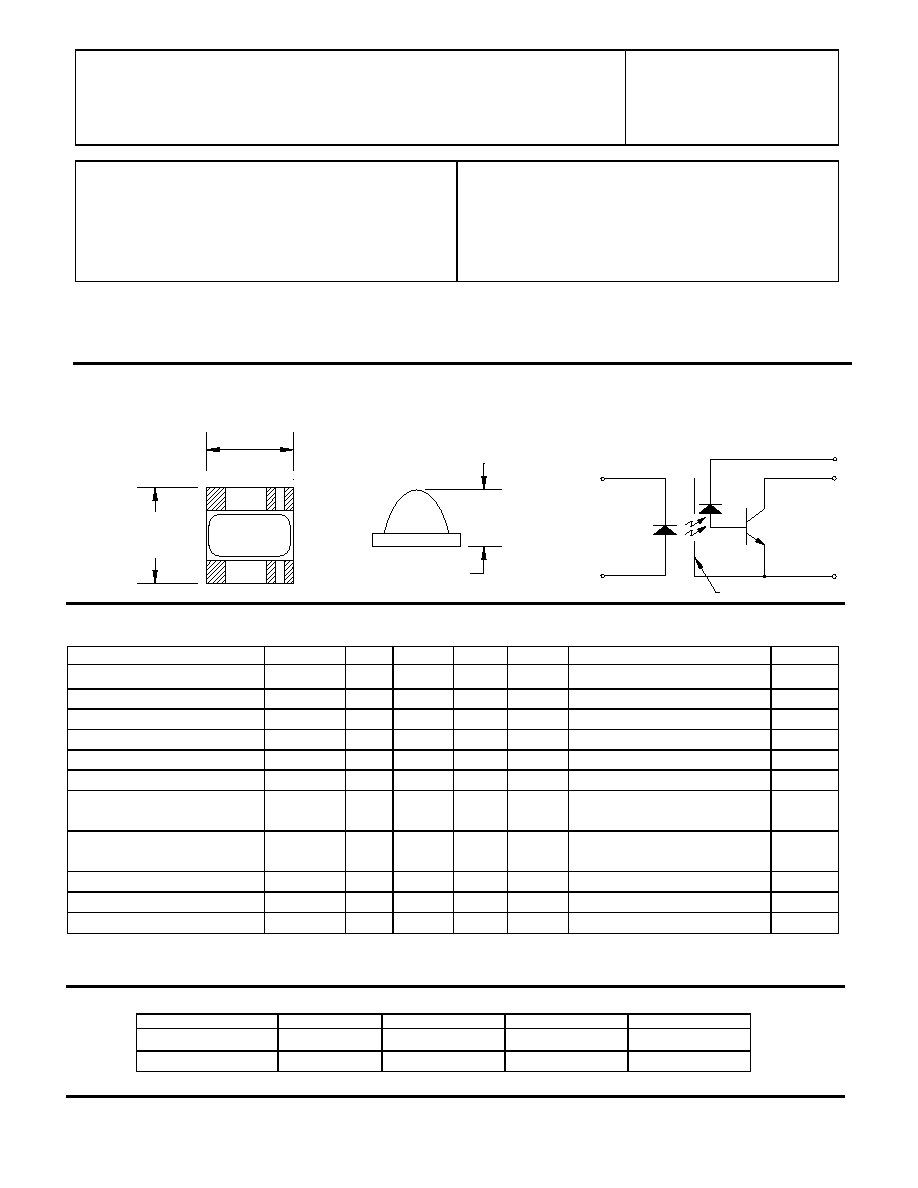
Package Dimensions Schematic Diagram
K
A
6
1
Vcc
4
Vo
3
0.100±0.010
[2.54±0.25]
1
2
3
6
4
5
0.110±0.10
[2.79±0.25]
5
GND
SHIELD
0.065 Max
ELECTRICAL CHARACTERISTICS
T
a
= -55
∞
C to 125
∞
C unless otherwise specified.
PARAMETER
SYMBOL
MIN
TYP
MAX
UNITS
TEST CONDITIONS
NOTE
Current Transfer Ratio
CTR
9
20
%
I
F
= 16mA, V
O
= 0.4V , V
CC
= 4.5V
1
Logic High Output Current
I
OH
20
100
µ
A
I
F
= 250
µ
A, V
CC
= V
O
=18V
High Level Output Current
I
CCH
0.2
10
µ
A
I
F
= 0, V
CC
= 18V
Low Level Supply Current
I
CCL
35
200
µ
A
I
F1
= I
F2
= 20mA, V
CC
= 18V
Input Forward Voltage
V
F
1.5
1.8
V
I
F
= 20mA
Input Reverse Breakdown Voltage
BV
R
3
V
I
R
= 10µA
Propagation Delay Time To High
Output Level
t
PLH
2
6
µ
s
I
F
= 16mA, V
CC
= 5V, R
L
= 8.2k
C
L
= 50pF
Propagation Delay Time To Low
Output Level
t
PHL
0.4
2
µ
s
I
F
= 16mA, V
CC
= 5V, R
L
= 8.2k
C
L
= 50pF
Input Capacitance
C
IN
120
pF
V
F
= 0, f = MHz
Capacitance (Input-Output)
C
I-O
1.5
pF
f = 1MHz, V
F
= 0
2
Resistance (Input-Output)
R
I-0
10
12
V
I--O
= 500Vdc
NOTES:
1.
CURRENT TRANSFER RATIO is defined as the ratio of output collector current, I
O
, to the forward LED input current., I
F
, times 100%.
2.
Measured between input pins shorted together and the output pins for that channel shorted together.
RECOMMENDED OPERATING CONDITIONS:
PARAMETER
SYMBOL
MIN
MAX
UNITS
Input Current, Low Level
I
FL
0
2
µ
A
Supply Voltage
V
CC
2.0
18
V