Replacement of
LT1086-3.3/2.9/2.5
LT1085-3.3/2.9/2.5
MIK1086-3.3/2.9/2.5
MIK1085-3.3/2.9/2.5
1.5 A/3.0 A Low Dropout
Positive Regulator
August 1995-revised September 2002
Description
The MIK1086/MIK1085 Series 1.5/3.0A fixed voltage regulators are monolithic integrated circuits designed to power the new generation of
microprocessors for use applications requiring a well regulated positive output voltage with low input-output differential voltage requirements
and output voltage 3.3V, 2.9V or 2.5V. Output voltage may be selecting using a jumper on the circuit board. Outstanding features include full
power usage up to 1.5/3.0A of load current, internal current limiting and thermal shutdown. Other fixed versions are also available Vout =
2.0V to 4.0V.
Features
∑ Low Dropout Performance 1V at full Load
∑ Jumper Selected Output Voltage 3.3V, 2.9V, 2.5V
∑ Line Regulation Typically 0.015%
∑ Load Regulation Typically 0.1%
∑ Fast Transient Response
∑ 5 Lead TO-220 Packages
Applications
∑
Microprocessor Supplies
∑
Post Regulators for Switching Supplies
∑
High Current Regulators
∑
5V to 3.XXV for Pentium Processors
∑
3.3V to 2.5V for Portable Pentium Processors
∑
Power PC Series Power Supplies
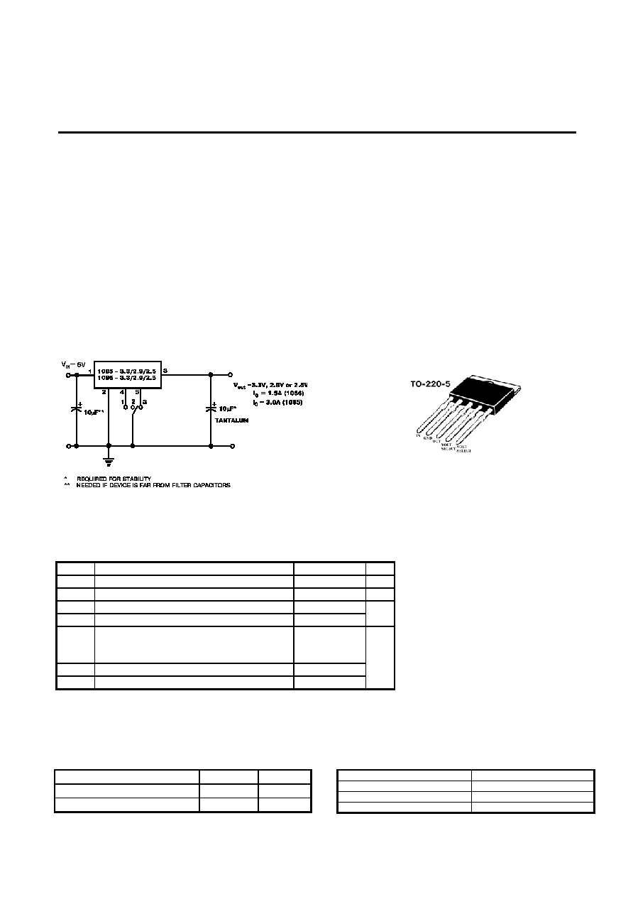
Typical application data fixed
regulator
Package information
Absolute Maximum Ratings
Symbol Parameter
Maximum
Units
V
IN
Input
Voltage
6
V
P
o
Power Dissipation
Internally Limited
W
JC
Thermal Resistance Junction to Case TO-220-5
3
JA
Thermal Resistance Junction to Ambient TO-220-5
50
o
C/W
T
J
Operating Junction Temperature Range
Control Section
Power Transistor
0 to 125
0 to 150
T
STG
Storage Temperature Range
-65 to 150
T
LEAD
Lead Temperature (Soldering 10 Sec.)
260
o
C
Device Selection Guide
Device
Vout, V
Iout, A
MIK1086
3.3, 2.9, 2.5
1.5
MIK1085
3.3, 2.9, 2.5
3.0
Output voltage selecting
Jumper V
OUT
, V
1 2.9
2 3.3
3 2.5
Page 1 of 2
Replacement of
LT1086-3.3/2.9/2.5
LT1085-3.3/2.9/2.5
MIK1086-3.3/2.9/2.5
MIK1085-3.3/2.9/2.5
1.5 A/3.0 A Low Dropout
Positive Regulator
August 1995-revised September 2002
Electrical Characteristics
(V
IN
= 4.75V to 5.25V; I
O
= 10mA to 3.0A(MIK1085); I
O
= 10mA to 1.5A(MIK1086), Unless otherwise specified)
Test Conditions
Test Limits
Parameter Symbol
V
IN
I
O
T
J
(Note 3) Min Typ
Max
Units
10mA 25∫C
3.267
3.333
V
0
(3.3V)
5V
Over
Temp.
3.234
3.3
3.366
10mA 25∫C
2.871
2.929
V
0
(2.9V)
5V
Over
Temp.
2.842
2.9
2.958
10mA 25∫C
2.475
2.525
Output Voltage
V
0
(2.5V)
5V
Over
Temp.
2.450
2.5
2.550
V
25∫C 0.015
Line Regulation (Note 1)
REG
(LINE)
10mA
Over Temp.
0.035
0.2
25∫C 0.1
0.3
Load Regulation (Note 1)
REG
(LOAD)
5V
Over Temp.
0.2
0.4
%
25∫C 1.0
Dropout Voltage
V
OUT =
2%
V
D
Over Temp.
1.1 1.3
V
Current Surge Limit
MIK1085
MIK1086
I
S
4.5
2.5
A
Quiescent current
I
Q
5V
10
16
mA
Temperature Coefficient
T
C
0.005
%/∫C
Temperature Stability
T
S
5V 0.5A
0.5 %
RMS Output Noise (Note2)
V
N
25∫C
0.003
%V
o
Ripple Rejection Ratio
MIK1085
MIK1086
R
A
5V
3.0A
1.5A
Over Temp.
60
72
dB
Note 1: Low duty cycle pulse testing.
Note 2: Bandwidth of 10Hz to 10kHz.
Note 3: Over Temp. = over specified operating junction temperature range.
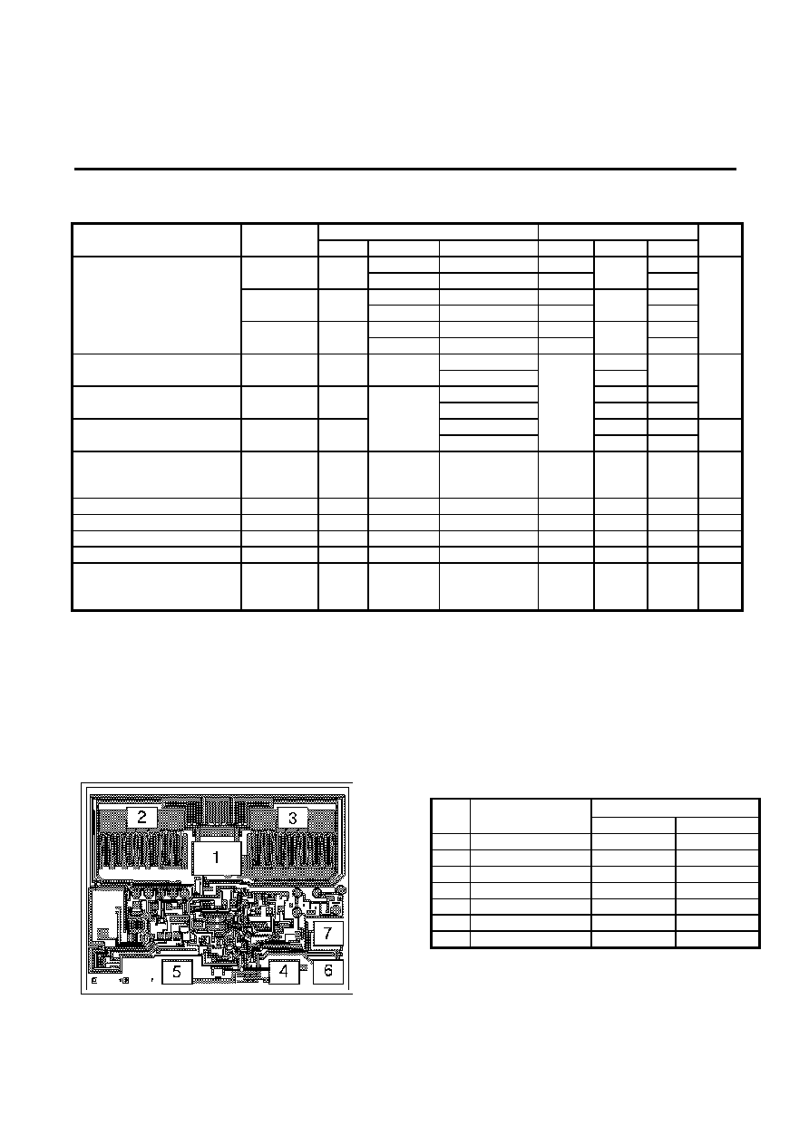
Pad Location LT1085-3.3/2.9/2.5; LT1086-3.3/2.9/2.5
Pad location coordinates
Coordinates µm
N Pad
name
X Y
1 Input
1275
1360
2 Output
520
1890
3 Output
2245
1890
4 Output
2155
120
5 GND
930 120
6 Select
2.9V
2655
120
7 Select
2.5V
2660
560
Page 2 of 2