Replacement of
KA2410/KA2411
MIK2410/MIK2411
Tone Ringers
February 1995 - revised October 1999
Description
The MIK2410/ MIK2411 is a bipolar integrated circuits for telephone tone ringer.
These devices consists of an output amplifier, two oscillators, and power supply control circuit.
Features
∑
Low current drain
∑
Adjustable 2 tone frequency
∑
Hysteresis circuit prevent false triggering and rotary dial
ęChirpsĽ
∑
8 pin DIP plastic package
∑
External triggering or ringer disable (MIK2410)
∑
Adjustable for reduced supply initiation current (MIK2411)
Applications
∑
Telephone bell replacement
∑
Extension tone ringer modules
∑
Alarms or other alerting devices
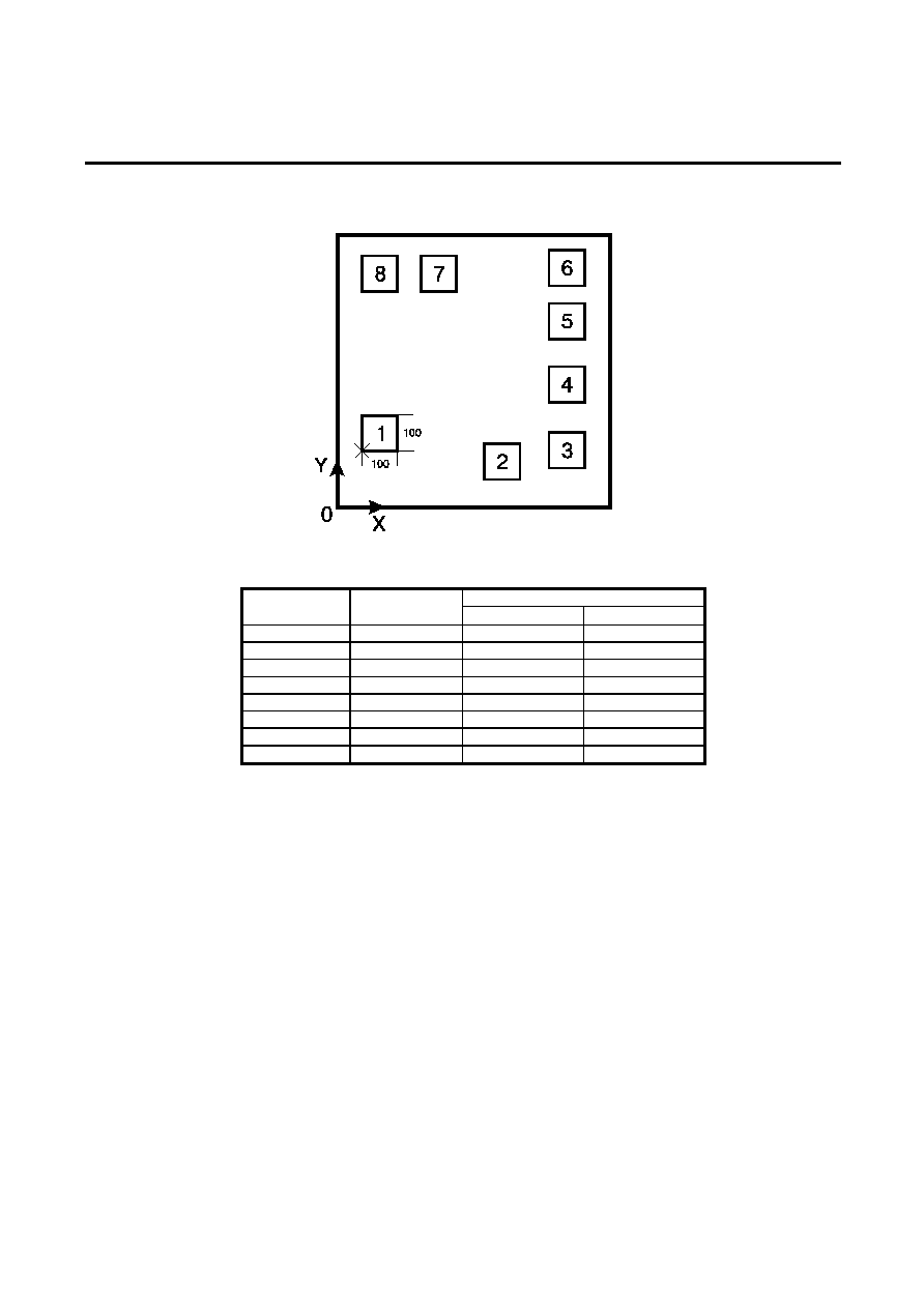
Pin Configuration
(TOP VIEW)
Pin Assignment
Pin Name
Function
1 V
CC
Power
supply
2 RSL
Resistor
select
3
LFI
Low freq. osc. input
4
LFO
Low freq. osc. output
5 GND
Ground
6
HFO
High freq. osc. output
7
HFI
High freq. osc. input
8 OUT
Output
Absolute Maximum Ratings
Parameter Symbol
Rating
Units
DC Supply voltage
V
CC
36
V
Power Dissipation
P
d
450
mW
Operating Ambient Temperature Range
T
A
-25...+75
Storage Temperature Range
T
STG
-65...+150
įC
Note 1: Voltage values are with respect to the anode terminal unless otherwise noted
Electrical characteristics
(V
CC
=24V, T
a
=25įC, unless otherwise noted)
Parameter Symbol
Test
Conditions
Min
Typ
Max
Units
Operating Voltage
V
CC
36
V
SI
(Note 1)
17
19
21
V
Supply Initiation
Voltage
Current
I
SI
V
CC
=V
SI
, No load
1.4
2.5
4.2
mA
Sustaining
Voltage
V
SUS
(Note 2)
9.7
10.5
12
V
Current
I
SUS
V
CC
=V
SUS
, No load
0.2
0.9
2.5
mA
Oscillator Freq. (Note 3)
f
L
R1=165k
, C1=0.47ĶF
9 10
11 Hz
Oscillator Freq. (Note 3)
f
H1
R2=191k
, C2=6800pF
461 512 563 Hz
Oscillator Freq. (Note 3)
f
H2
R2=191k
, C2=6800pF
576 640 703 Hz
Output
High Voltage
V
OH
V
CC
=21V
I
OH
=15mA
17.7
19
21.5
Low Voltage
V
OL
I
OL
=15mA
1.6
V
Trigger
Voltage (Note 4)
V
TRG
V
CC
=15V
8.5
10.5
V
Current (Note 5)
I
TRG
MIK2410 Only (2 pin)
20
1000
ĶA
Disable
Voltage
V
DIS
0.4
0.8
V
Current (Note 6)
I
DIS
MIK2410 Only (2 pin)
-40
-20
ĶA
Note 1: Supply initiation voltage is the value of DC supply voltage required to start the tone ringer oscillating.
Note 2: Sustaining voltage is the value of DC supply voltage required to maintain the oscillation.
Note 3: Oscillator frequency is determined by the following equations:
f
L
=1/(1.359xR1xC1) (Hz)
f
HI
=1/(1.518xR2xC2) (Hz)
f
H2
=1.214xf
HI
(Hz)
Note 4: V
tr
and I
tr
the conditions applied to trigger input to start oscillation for V
sus
V
CC
V
si.
Note 5: Trigger current must be limited to this value externally.
Note 6: V
dis
and I
dis
are the conditions applied to trigger input to inhibit oscillation for V
si
V
CC.
Page 1 of 4
Replacement of
KA2410/KA2411
MIK2410/MIK2411
Tone Ringers
February 1995 - revised October 1999
f=20Hz
T
R
6.2k
1 F
250V
Ķ
10 F
50V
Ķ
27V
+
RSL
220k
R1
C1
220nF
1
2
3
4
5
6
7
8
R2 180k
C2
4.7nF
1 F
50V
Ķ
470k
+
10k
~
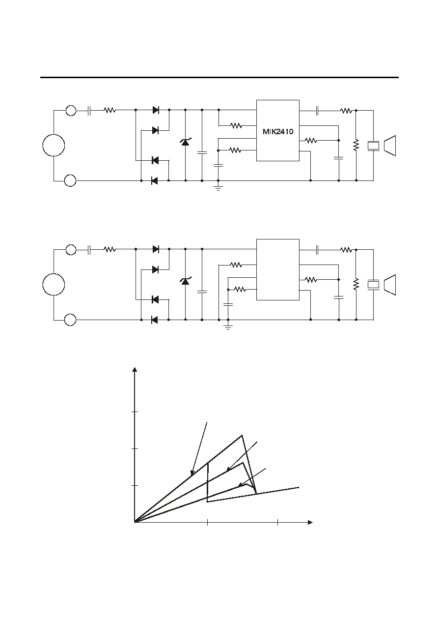
Figure 1. Application Circuit for MIK2410
f=20Hz
T
R
6.2k
1 F
250V
Ķ
10 F
50V
Ķ
27V
+
RSL
220k
R1
C1
220nF
MIK2411
1
2
3
4
5
6
7
8
R2 180k
C2
4.7nF
10 F
50V
Ķ
470k
+
10k
~
Figure 2. Application Circuit for MIK2411
Shown the supply initiation current (Isi) can be
changed using the RSL pin.
RSL=6.2k
RSL=10k
RSL=15k
I
CC
V
CC
[mA]
[V]
Figure 3. Use of RSL pin (for MIK2411 only)
3
2
1
0
10
20
Page 2 of 4

Replacement of
KA2410/KA2411
MIK2410/MIK2411
Tone Ringers
February 1995 - revised October 1999
Pad Location MIK2410/MIK2411
(See Note 1)
Chip size 1.45x1.45 mm
Pad Location Coordinates
Coordinates
Pad N
Pad Name
X (
Ķm)
Y (
Ķm)
1
VCC
95
270
2A
RSL
925
90
2B
690
90
3
LFI
1245
90
4
LFO
1245
490
5
GND
1245
765
6
HFO
1245
1185
7
HFI
460
1185
8
OUT
95
1185
Note 1: For MIK2410 2A pad to be used, 2B pad not connected; for MIK2411 2B
pad to be used, 2A pad not connected.
Page 3 of 4