INTERNET http://www.minicircuits.com
P.O. Box 350166, Brooklyn, New York 11235-0003 (718) 934-4500 Fax (718) 332-4661
Distribution Centers
NORTH AMERICA 800-654-7949 ∑ 417-335-5935 ∑ Fax 417-335-5945 ∑ EUROPE 44-1252-832600 ∑ Fax 44-1252-837010
Mini-Circuits
Æ
ISO 9001 CERTIFIED
REV. B
M89969
D60-1117.DOC
Gali-19 Q0201030
Gali-29 Q0201031
Gali-39 Q0201032
Gali-49 EC-9381/10
Gali-59 EC-9381/11
RS/TD/CP
031202
Features
∑ miniature SOT-89 package
∑ frequency range, DC to 7 GHz
∑ up to 17.6 dBm typ. output power
∑ excellent package for heat dissipation, exposed metal bottom
50
, Broadband,
DC to 7 GHz
Electrical Specifications @ 25∞C
Maximum Ratings
Operating Temperature
-45∞C to 85∞C
Storage Temperature
-65∞C to 150∞C
Applications
∑ cellular
∑ PCS
∑ communication receivers & transmitters
FREQ.
s
s
s
s
s
(GHz)
MODEL
NO.
Gali
19
DC-7
12.1
11.7
11.6
10.7
10.8
10.1
11.0
14.5
9.6
10.6
9.0
15
6.5
23.7
1.6
1.7
1.5
2.3
55
40
3.6 3.2 4.0
311
1.19
Gali
29
DC-7
15.4
15.1
14.7
13.7
13.6
12.9
14.2
12.5
12.7
11.2 10.0
15
6.0
24.7
1.5
1.6
1.5
2.3
55
40
3.6 3.2 4.0
340
1.19
Gali
39
DC-7
20.8
21.1
19.7
17.7
17.0
16.1
17.6
9.8
17.7
10.5
9.0
13
4.9
22.9
1.6
1.8
1.5
2.3
55
35
3.5 3.1 3.9
350
1.19
Gali
49
DC-5
14.0
13.7
13.6
13.7
13.3
13.1
10.7 --
11.5
16.4 15.0
20
5.5
33.3
1.7
1.2
1.5
1.4
85
65
5.0 4.5 5.4
171
1.79
Gali
59
DC-5
20.6
19.7
18.3
16.7
15.4
14.0
10.2 --
16.3
17.6 16.5
13.0
4.3
33.3
1.6
1.5
1.5
1.7
85
65
4.8 4.3 5.2
209
1.79
f
L
- f
U
DC
OPERATING
POWER
@ Pin 3***
VSWR
(:1)
Typ.
DYNAMIC
RANGE
at 2 GHz*
NF
dB
Typ.
IP3
dBm
Typ.
MAXIMUM
POWER, dBm
at 7 GHz*
Input
(no
dmg.)
Output
(1 dB
Comp.)
Typ. Min.
1
0.1
Min.
@
2 GHz
GAIN, dB Typical
over frequency, GHz
2
4
5
7
10
MAXIMUM
CURRENT
RATING**
Out
DC-3
GHz
3-f
U
GHz
THERMAL
RESIS-
TANCE
In
Cur-
rent
(mA)
Device
Volt
Typ Min Max
jc,
typ.
∞C/W
I
mA
DC-3
GHz
PRICE
$
Qty.
(25)
3-f
U
GHz
f
U
is the upper frequency limit for each model as shown in the table.
v
v
v
v
v
Low frequency cutoff determined by external coupling capacitors.
* For Pout @ 1dB compression, Gali-49,-59 at 2 GHz.
For IP3, Gali-49,-59 at 1 GHz.
** Permanent damage may occur if any of these limits are exceeded.
These ratings are not intended for continuous normal operation.
***Reliability predictions and normal operating conditions are applicable at
current specified.
Prefix letter (optional) designates assembly
location. Suffix letters (optional) are for
wafer identification.
Page 1 of 2
Pin Configuration
RF IN
1
RF OUT
3
DC
3
GND EXT.
2
Model Identification
Model
Marking
Gali-19
19
Gali-29
29
Gali-39
39
Gali-49
49
Gali-59
59
Gali
19 ∑ Gali
29 ∑ Gali
39
Gali
49 ∑ Gali
59
NEW!
1
1
10
10
100
100
1,000
1,000
MTTF (Years)
M
T
T
F
(
Y
e
a
r
s
)
140
140
160
160
180
180
200
200
220
220
Junction Temp (
Junction Temp (∞C)
C)
MTTF vs. Junction Temp.
MTTF vs. Junction Temp.
3
MEDIUM
POWER
LOW
POWER
CASE STYLE : DF782
Monolithic Amplifiers
Surface Mount
INTERNET http://www.minicircuits.com
P.O. Box 350166, Brooklyn, New York 11235-0003 (718) 934-4500 Fax (718) 332-4661
Distribution Centers
NORTH AMERICA 800-654-7949 ∑ 417-335-5935 ∑ Fax 417-335-5945 ∑ EUROPE 44-1252-832600 ∑ Fax 44-1252-837010
Mini-Circuits
Æ
ISO 9001 CERTIFIED
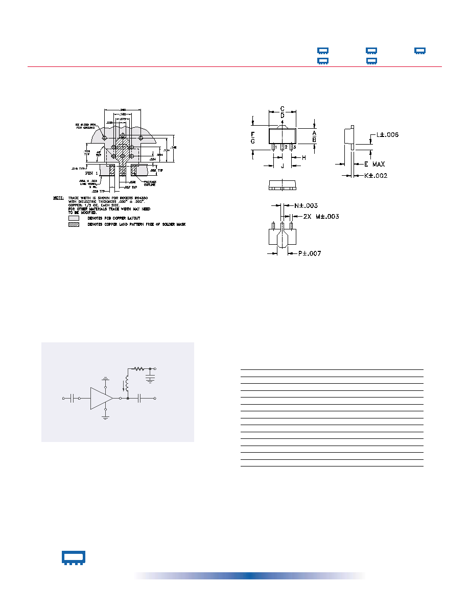
A
B
C
D
E
F
G
H
.102
.090
.181
.173
.063
.167
.155
.059
2.59
2.29
4.60
4.39
1.60
4.24
3.94
1.50
J
K
L
M
N
P
wt.
.118
.015
.041
.016
.019
.065
grams
3.00
0.38
1.04
0.41
0.48
1.65
.2
Outline Drawing
Suggested Layout for PCB Pattern
Outline Dimensions
(
)
inch
inch
inch
inch
inch
mm
mm
mm
mm
mm
Page 2 of 2
R BIAS
"1%" Resistor Values (ohms) for Optimum Biasing of Gali Models
Vcc
Gali-19
Gali-29
Gali-39
Gali-49
Gali-59
7
88.7
88.7
107
34.0
36.5
8
113
113
133
48.7
51.1
9
137
137
162
64.9
64.9
10
162
162
191
80.6
80.6
11
187
187
221
95.3
97.6
12
215
215
249
110
113
13
237
237
280
127
127
14
261
261
309
143
143
15
287
287
340
158
158
16
309
316
365
174
174
17
332
340
392
187
191
18
357
365
422
205
205
19
383
392
453
221
221
20
412
412
475
237
237
Gali
19 ∑ Gali
29 ∑ Gali
39
Gali
49 ∑ Gali
59
Typical Biasing Configuration
4
2
3
1
Cblock
IN
Cblock
Ibias
OUT
Vd
RFC (Optional)
Cbypass
Vcc
Rbias (Required)
Test Board includes case, connectors, and components (in bold)
soldered to PCB