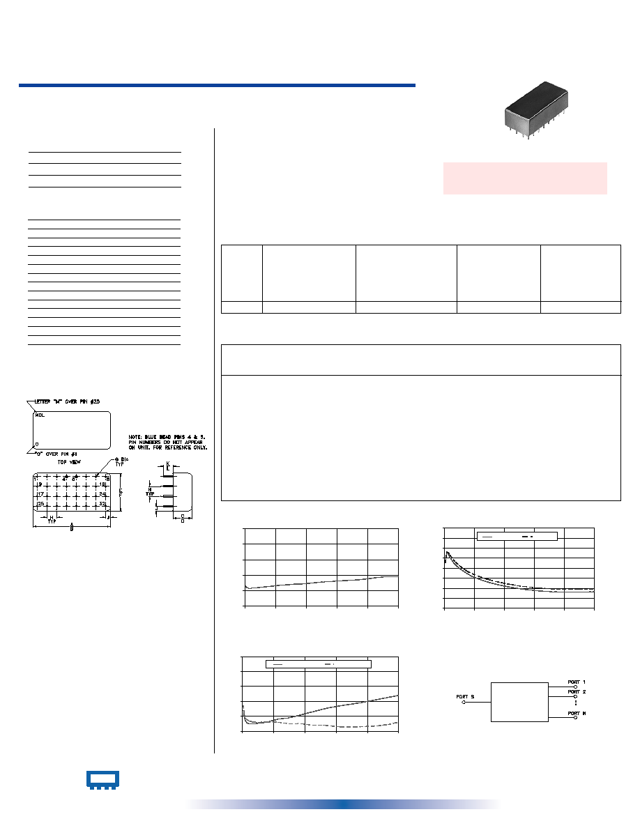
12 Way-0∞ 50
1 to 200 MHz
Power Splitter/Combiner
Plug-In
PSC-12-1+
PSC-12-1
CASE STYLE: E10
PRICE: $93.45 ea. QTY (1-9)
PSC-12-1
INSERTION LOSS
10
11
12
13
14
15
0
40
80
120
160
200
FREQUENCY (MHz)
INS
E
RT
IO
N LO
S
S
(
d
B
)
PSC-12-1
ISOLATION
20
25
30
35
40
45
50
55
60
0
40
80
120
160
200
FREQUENCY (MHz)
IS
O
L
A
T
IO
N (
d
B
)
1-2(dB)
2-4(dB)
PSC-12-1
VSWR
1.0
1.1
1.2
1.3
1.4
1.5
0
40
80
120
160
200
FREQUENCY (MHz)
VSWR
#S-VSWR
#12-VSWR
Outline Dimensions ( )
inch
mm
Maximum Ratings
Features
∑ HF/VHF
∑ communication systems
∑ signal processing
∑ low insertion loss, 0.8 dB typ.
∑ good isolation, 27 dB typ.
∑ rugged, welded case
Applications
Operating Temperature
-55∞C to 100∞C
Storage Temperature
-55∞C to 100∞C
Power Input (as a splitter)
1W max.
Internal Dissipation
0.87W max.
Outline Drawing
Splitter Electrical Specifications
L
Typ. Min.
M
Typ. Min.
U
Typ. Min.
FREQ.
RANGE
(MHz)
PHASE
UNBALANCE
(Degrees)
L
Max.
U
Max.
M
Max.
ISOLATION
(dB)
INSERTION LOSS (dB)
ABOVE 10.8 dB
L
Typ. Max.
M
Typ. Max.
U
Typ. Max.
AMPLITUDE
UNBALANCE
(dB)
L
Max.
U
Max.
M
Max.
f
L
-f
U
1-200
35
30
27
20
21
18
0.5
0.8
0.8
1.2
1.0
1.4
4
8
16
0.2
0.4
0.7
INTERNET http://www.minicircuits.com
P.O. Box 350166, Brooklyn, New York 11235-0003 (718) 934-4500 Fax (718) 332-4661
Distribution Centers
NORTH AMERICA 800-654-7949 ∑ 417-335-5935 ∑ Fax 417-335-5945 ∑ EUROPE 44-1252-832600 ∑ Fax 44-1252-837010
Mini-Circuits
Æ
Mini-Circuits ISO 9001 & ISO 14001 Certified
REV. A
M98898
PSC-12-1
HY/TD/CP/AM
060711
L = low range [f
L
to 10 f
L
]
M = mid range [10 f
L
to f
U
/2] U = upper range [f
U
/2 to f
U
]
Pin Connections
SUM PORT
5
PORT 1
7
PORT 2
8
PORT 3
1
PORT 4
2
PORT 5
31
PORT 6
32
PORT 7
25
PORT 8
26
PORT 9
22
PORT 10
30
PORT 11
19
PORT 12
27
GROUND
all other pins
CASE GROUND
3,6
Insertion Loss
(dB)
VSWR
S
VSWR
12
Isolation
(dB)
2-4
Amplitude
Unbalance
(dB)
1-2
Frequency
(MHz)
Typical Performance Data
A
B
C
D
E
F
G
1.580
1.620
.380
.410
.770
.810
.030
40.13
41.15
9.65
10.41
19.56
20.57
0.76
H
J
K
L
wt
.200
.10
.20
.14
grams
5.08
2.54
5.08
3.56
23.0
Phase
Unbalance
(deg.)
1.00
11.30
0.16
42.68
42.83
0.40
1.14
1.17
3.00
11.19
0.14
47.69
47.94
0.18
1.08
1.09
5.00
11.17
0.14
46.95
47.73
0.14
1.06
1.08
8.00
11.17
0.13
45.01
46.14
0.23
1.05
1.07
15.00
11.20
0.14
41.53
42.92
0.40
1.05
1.06
30.00
11.27
0.13
37.29
38.55
0.67
1.06
1.06
45.00
11.35
0.14
34.70
36.08
0.97
1.08
1.06
60.00
11.41
0.14
32.86
34.20
1.42
1.09
1.05
75.00
11.45
0.14
31.48
32.85
1.65
1.11
1.05
90.00
11.52
0.16
30.40
31.78
1.96
1.13
1.04
105.00
11.58
0.14
29.57
30.96
2.21
1.15
1.04
125.00
11.64
0.15
28.75
30.17
2.68
1.17
1.03
150.00
11.72
0.14
28.20
29.63
3.19
1.19
1.03
180.00
11.89
0.18
28.08
29.45
3.99
1.22
1.04
200.00
11.91
0.21
28.33
29.66
4.45
1.24
1.06
electrical schematic
+ RoHS compliant in accordance
with EU Directive (2002/95/EC)
The + suffix identifies RoHS Compliance. See our web site
for RoHS Compliance methodologies and qualifications.