3 Way-0∞ 50
5 to 500 MHz
Power Splitter/Combiner
Plug-In
PSC-3-1W+
PSC-3-1W
CASE STYLE: A01
PRICE: $40.20 ea. QTY (1-9)
PSC-3-1W
INSERTION LOSS
5.0
5.2
5.4
5.6
5.8
6.0
0
100
200
300
400
500
FREQUENCY (MHz)
I
N
SER
T
I
O
N
LO
SS (
d
B)
S-1(dB)
S-2(dB)
S-3(dB)
PSC-3-1W
ISOLATION
20
24
28
32
36
40
0
100
200
300
400
500
FREQUENCY (MHz)
IS
O
L
A
T
IO
N (
d
B
)
1-2 (dB)
1-3 (dB)
2-3 (dB)
PSC-3-1W
VSWR
1.0
1.1
1.2
1.3
1.4
1.5
0
100
200
300
400
500
FREQUENCY (MHz)
VSWR
#S-VSWR
#1-VSWR
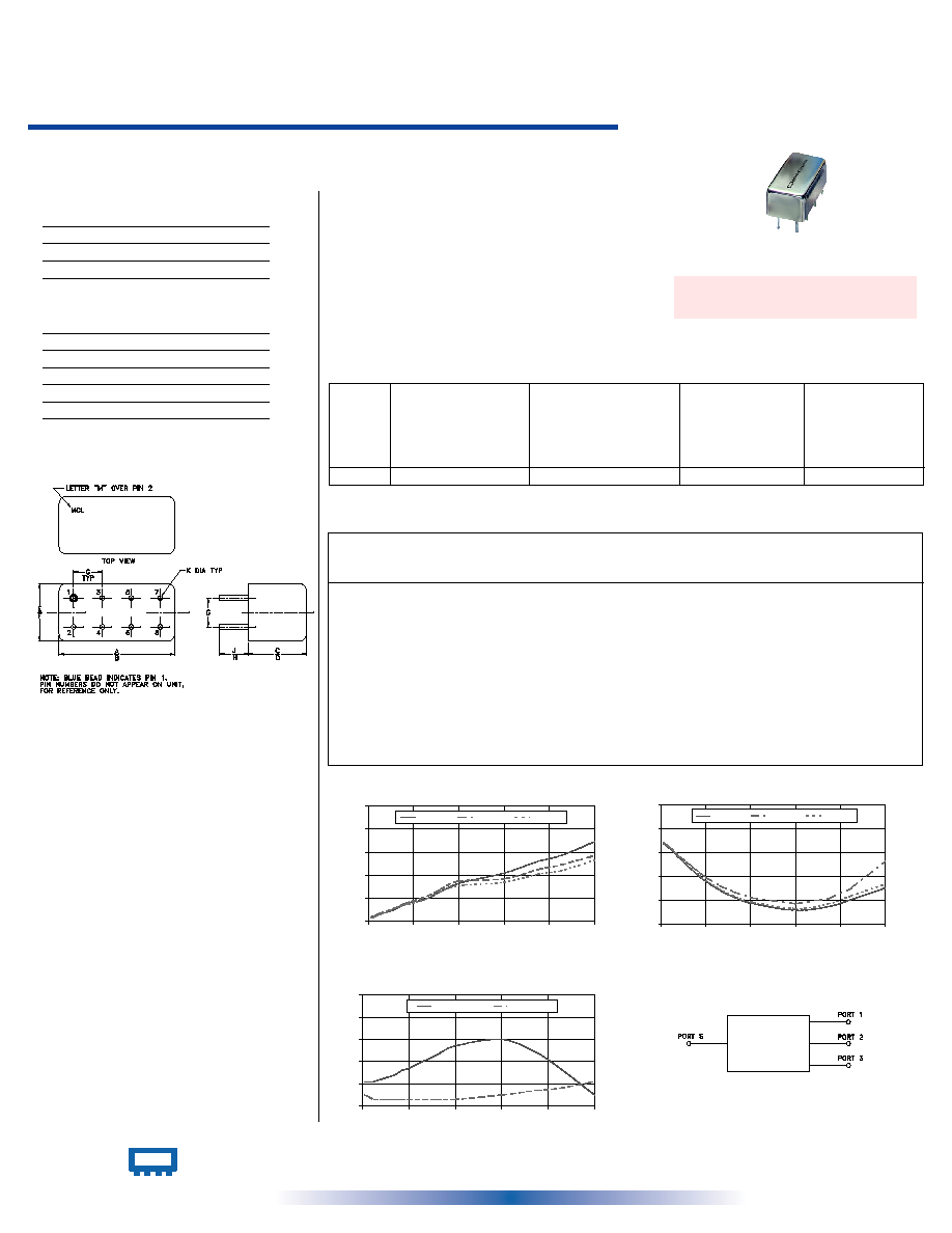
Outline Dimensions ( )
inch
mm
Maximum Ratings
Pin Connections
Features
∑ VHF/UHF
∑ communication systems
SUM PORT
1
PORT 1
5
PORT 2
7
PORT 3
8
GROUND
2,3,4,6
CASE GROUND
2,3,4,6
∑ wideband, 5 to 500 MHz
∑ low insertion loss, 0.4 dB typ.
∑ good isolation, 31 dB typ.
∑ rugged welded construction
Applications
Operating Temperature
-55∞C to 100∞C
Storage Temperature
-55∞C to 100∞C
Power Input (as a splitter)
1W max.
Internal Dissipation
0.375W max.
Outline Drawing
Splitter Electrical Specifications
L
Typ. Min.
M
Typ. Min.
U
Typ. Min.
FREQ.
RANGE
(MHz)
PHASE
UNBALANCE
(Degrees)
L
Max.
U
Max.
M
Max.
ISOLATION
(dB)
INSERTION LOSS (dB)
ABOVE 4.8 dB
L
Typ. Max.
M
Typ. Max.
U
Typ. Max.
AMPLITUDE
UNBALANCE
(dB)
L
Max.
U
Max.
M
Max.
f
L
-f
U
5-500
25
20
31
15
25
15
0.4
0.8
0.4
1.4
0.8
1.4
2
3
5
0.1
0.3
0.6
INTERNET http://www.minicircuits.com
P.O. Box 350166, Brooklyn, New York 11235-0003 (718) 934-4500 Fax (718) 332-4661
Distribution Centers
NORTH AMERICA 800-654-7949 ∑ 417-335-5935 ∑ Fax 417-335-5945 ∑ EUROPE 44-1252-832600 ∑ Fax 44-1252-837010
Mini-Circuits
Æ
Mini-Circuits ISO 9001 & ISO 14001 Certified
REV. A
M98898
PSC-3-1W
HY/TD/CP
060711
L = low range [f
L
to 10 f
L
]
M = mid range [10 f
L
to f
U
/2] U = upper range [f
U
/2 to f
U
]
A
B
C
D
E
F
.770
.800
.385
.400
.370
.400
19.56
20.32
9.78
10.16
9.40
10.16
G
H
J
K
wt
.200
.20
.14
.031
grams
5.08
5.08
3.56
0.79
5.2
Typical Performance Data
Freq.
(MHz)
Insertion Loss
(dB)
Amp.
Unbal.
(dB)
Isolation
(dB)
S-1
S-2
S-3
1-2
2-3
VSWR
S
Phase
Unbal.
(deg.)
VSWR
2
VSWR
3
VSWR
1
1-3
5.00
5.04
5.04
5.03
0.01
33.54
33.69
33.71
0.04
1.11
1.05
1.05
1.05
15.00
5.05
5.04
5.05
0.01
32.96
33.10
33.16
0.09
1.11
1.04
1.04
1.04
25.00
5.07
5.07
5.06
0.01
32.27
32.48
32.49
0.14
1.11
1.03
1.03
1.03
40.00
5.08
5.09
5.08
0.01
31.09
31.45
31.26
0.26
1.12
1.03
1.03
1.03
55.00
5.10
5.11
5.11
0.01
30.01
30.47
30.15
0.27
1.13
1.03
1.03
1.03
70.00
5.13
5.14
5.13
0.01
29.01
29.58
29.14
0.40
1.14
1.03
1.03
1.03
85.00
5.16
5.16
5.15
0.01
28.01
28.66
28.14
0.54
1.16
1.03
1.03
1.03
100.00
5.17
5.18
5.16
0.01
27.15
27.83
27.31
0.50
1.17
1.03
1.02
1.02
130.00
5.20
5.22
5.20
0.02
25.71
26.47
25.85
0.65
1.20
1.03
1.02
1.02
160.00
5.26
5.28
5.26
0.02
24.61
25.45
24.77
0.87
1.23
1.03
1.02
1.02
200.00
5.33
5.35
5.31
0.03
23.50
24.43
23.72
0.88
1.27
1.03
1.02
1.02
300.00
5.42
5.37
5.34
0.08
22.32
23.39
22.61
1.41
1.30
1.05
1.05
1.06
375.00
5.52
5.45
5.41
0.11
22.95
24.29
23.40
1.69
1.24
1.07
1.08
1.09
425.00
5.57
5.49
5.44
0.12
24.12
26.01
24.77
1.87
1.17
1.08
1.11
1.11
500.00
5.69
5.57
5.53
0.16
26.04
30.58
26.69
2.05
1.05
1.11
1.14
1.14
electrical schematic
+ RoHS compliant in accordance
with EU Directive (2002/95/EC)
The + suffix identifies RoHS Compliance. See our web site
for RoHS Compliance methodologies and qualifications.