6 Way-0∞ 75
1 to 300 MHz
Power Splitter/Combiner
Plug-In
PSC-6-1-75
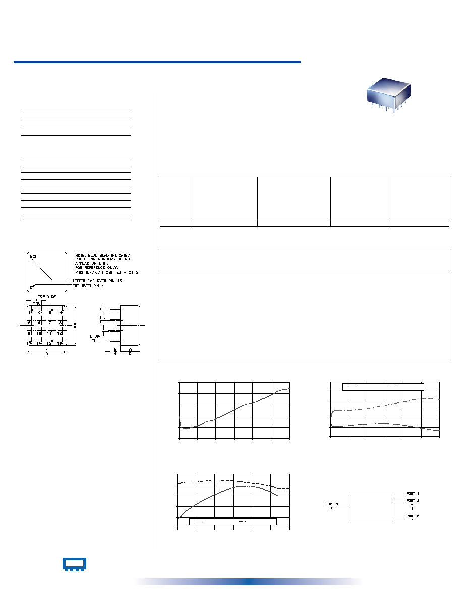
CASE STYLE: C07
PRICE: $83.45 ea. QTY (1-9)
Maximum Ratings
Pin Connections
Features
∑ VHF
∑ radio communication
∑ instrumentation
SUM PORT
1
PORT 1
3
PORT 2
4
PORT 3
8
PORT 4
12
PORT 5
16
PORT 6
15
GROUND
2,5,7,11,13,14
NOT USED
6,9,10
CASE GROUND
2,5,7,11,13,14
∑ low insertion loss, 0.6 dB typ.
∑ high isolation, 30 dB typ.
∑ excellent amplitude unbalance, 0.3 dB typ.
∑ rugged, welded case
Applications
Operating Temperature
-55∞C to 100∞C
Storage Temperature
-55∞C to 100∞C
Power Input (as a splitter)
1W max.
Internal Dissipation
0.5W max.
Splitter Electrical Specifications
INTERNET http://www.minicircuits.com
P.O. Box 350166, Brooklyn, New York 11235-0003 (718) 934-4500 Fax (718) 332-4661
Distribution Centers
NORTH AMERICA 800-654-7949 ∑ 417-335-5935 ∑ Fax 417-335-5945 ∑ EUROPE 44-1252-832600 ∑ Fax 44-1252-837010
Mini-Circuits
Æ
Mini-Circuits ISO 9001 & ISO 14001 Certified
REV. OR
M96283
PSC-6-1-75
HY/TD/CP
060711
L
Typ. Min.
M
Typ. Min.
U
Typ. Min.
FREQ.
RANGE
(MHz)
PHASE
UNBALANCE
(Degrees)
L
Max.
U
Max.
M
Max.
ISOLATION
(dB)
INSERTION LOSS (dB)
ABOVE 7.8 dB
L
Typ. Max.
M
Typ. Max.
U
Typ. Max.
AMPLITUDE
UNBALANCE
(dB)
L
Max.
U
Max.
M
Max.
f
L
-f
U
1-300
35
25
30
23
25
18
0.6
1.2
0.6
1.1
0.6
1.3
2
4
8
0.2
0.3
0.6
L = low range [f
L
to 10 f
L
]
M = mid range [10 f
L
to f
U
/2] U = upper range [f
U
/2 to f
U
]
PSC-6-1-75
INSERTION LOSS
8.0
8.2
8.4
8.6
8.8
9.0
0
50
100
150
200
250
300
FREQUENCY (MHz)
INS
E
RT
IO
N LO
S
S
(
d
B
)
PSC-6-1-75
ISOLATION
20
25
30
35
40
45
50
0
50
100
150
200
250
300
FREQUENCY (MHz)
IS
O
L
A
T
IO
N (
d
B
)
ADJACENT
OPPOSITE
PSC-6-1-75
VSWR
1.0
1.1
1.2
1.3
1.4
1.5
0
50
100
150
200
250
300
FREQUENCY (MHz)
VSWR
#S VSWR
#OUTPUTS
Typical Performance Data
Frequency
(MHz)
Insertion Loss
(dB)
Amplitude
Unbalance
(dB)
Isolation
(dB)
VSWR
S
Adjacent
Opposite
VSWR
OUTPUTS
1.00
8.39
0.04
26.90
30.03
1.10
1.42
2.00
8.31
0.10
26.50
31.48
1.09
1.42
5.00
8.21
0.09
25.77
33.43
1.10
1.42
10.00
8.19
0.12
25.58
34.11
1.11
1.42
20.00
8.18
0.04
25.55
34.23
1.15
1.43
50.00
8.23
0.05
25.97
34.27
1.22
1.43
75.80
8.31
0.03
26.45
34.68
1.27
1.44
100.00
8.35
0.03
26.82
35.20
1.31
1.44
150.50
8.51
0.05
27.11
36.97
1.38
1.44
178.50
8.60
0.10
26.75
38.15
1.39
1.43
200.00
8.63
0.08
26.18
39.01
1.39
1.42
225.30
8.70
0.13
25.36
40.17
1.37
1.41
253.30
8.78
0.19
24.39
40.81
1.33
1.39
272.00
8.85
0.22
23.80
40.95
1.30
1.37
300.00
8.89
0.22
23.06
40.25
1.30
1.37
Outline Dimensions ( )
inch
mm
Outline Drawing
A
B
C
D
E
.770
.810
.380
.410
.030
19.56
20.57
9.65
10.41
0.76
F
G
H
wt
.200
.20
.14
grams
5.08
5.08
3.56
11.0
electrical schematic