L = low range [f
L
to 10 f
L
] M = mid range [10 f
L
to f
U
/2] U= upper range [f
U
/2 to f
U
]
At low range frequency band (f
L
to 10 f
L
), linearly derate maximum input power by 13 dB .
* Phase unbalance is 3 degrees max from f
L
to 3 f
L
FREQ.
RANGE
(MHz)
ISOLATION
(dB)
INSERTION LOSS (dB)
ABOVE 3.0 dB
PHASE
UNBALANCE
(Degrees)
AMPLITUDE
UNBALANCE
(dB)
f
L
-f
U
L
M
U
L
M
U
L
M
U
L
M
U
Typ. Min Typ. Min Typ. Min Typ. Max. Typ. Max. Typ. Max. Max.
Max.
Max.
Max.
Max.
Max.
0.01-20
35
25
30
25
25
18
0.3
0.8
0.2
0.5
0.3
0.6
1*
2
2.5
0.1
0.1
0.2
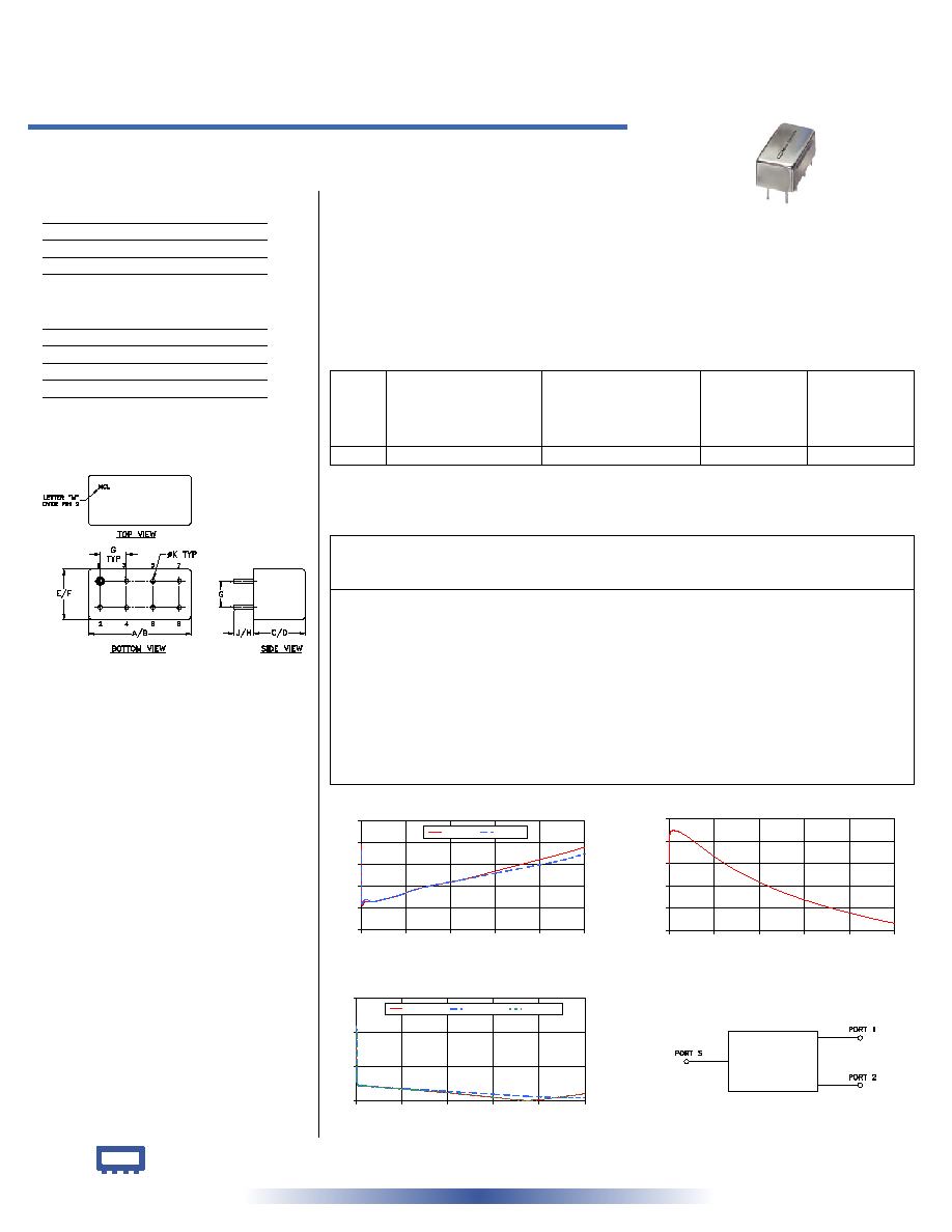
A
B
C
D
E
F
.770
.800
.385
.400
.370
.400
19.56 20.32
9.78 10.16
9.40 10.16
G
H
J
K
wt
.200
.20
.14
.031
grams
5.08
5.08
3.56
0.79
5.2
PSCJ-2-2
2 Way-180� 50 0.01 to 20 MHz
Power Splitter/Combiner
Plug-In
INTERNET
http://www.minicircuits.com
P.O. Box 350166, Brooklyn, New York 11235-0003 (718) 934-4500 Fax (718) 332-4661
Distribution Centers NORTH AMERICA 800-654-7949 � 417-335-5935 � Fax 417-335-5945 � EUROPE 44-1252-832600 � Fax 44-1252-837010
Mini-Circuits
�
Mini-Circuits ISO 9001 & ISO 14001 Certified
Typical Performance Data
Splitter Electrical Specifications
Maximum Ratings
Operating Temperature
-55�C to 100�C
Storage Temperature
-55�C to 100�C
Power Input (as a splitter)
1W max.
Internal Dissipation
0.125W max.
Outline Drawing
Outline Dimensions ( )
inch
mm
electrical schematic
REV. OR
M94845
PSCJ-2-2
HY/TD/CP
060915
CASE STYLE: A01
PRICE: $39.20 ea. QTY. (1-9)
Features
� low insertion loss, 0.2 dB typ.
� high isolation, 30 dB typ.
� excellent amplitude unbalance, 0.1 dB typ.
� excellent phase unbalance, 1 deg. typ.
� rugged shield case
Applications
� HF
� signal processing
� push-pull amplifiers
� radio communication
Pin Connections
SUMPORT
1
PORT 1
5
PORT 2
6
GROUND
2,3,4,7,8
CASE GROUND
2,3,4,7,8
PSCJ-2-2
INSERTION LOSS
3.0
3.1
3.2
3.3
3.4
3.5
0.0
4.0
8.0
12.0
16.0
20.0
FREQUENCY (MHz)
INSERTION
LOSS
(dB)
S-1(dB)
S-2(dB)
PSCJ-2-2
ISOLATION
20
24
28
32
36
40
0.0
4.0
8.0
12.0
16.0
20.0
FREQUENCY (MHz)
ISOLATION (dB)
PSCJ-2-2
VSWR
1.0
1.2
1.4
1.6
0.0
4.0
8.0
12.0
16.0
20.0
FREQUENCY (MHz)
V
S
W
R
#S-VSWR
#1-VSWR
#2-VSWR
Frequency
(MHz)
Insertion Loss
(dB)
Amplitude
Unbalance
(dB)
Isolation
(dB)
Phase
Unbalance
(deg.)
VSWR
S
VSWR
1
VSWR
2
S-1
S-2
0.01
3.39
3.36
0.02
31.98
179.30
1.43
1.44
1.43
0.05
3.12
3.12
0.00
37.15
179.74
1.12
1.11
1.12
0.10
3.11
3.12
0.01
37.79
179.85
1.10
1.09
1.10
0.40
3.13
3.14
0.01
37.95
180.04
1.09
1.09
1.09
0.80
3.13
3.13
0.01
37.77
180.06
1.09
1.09
1.09
1.20
3.13
3.13
0.01
37.38
180.06
1.09
1.08
1.09
2.00
3.14
3.14
0.01
36.31
180.10
1.08
1.08
1.08
3.50
3.16
3.16
0.00
34.01
180.18
1.07
1.07
1.07
4.50
3.18
3.18
0.00
32.59
180.23
1.07
1.07
1.07
6.00
3.20
3.20
0.00
30.71
180.31
1.06
1.06
1.06
9.00
3.23
3.23
0.00
27.76
180.47
1.04
1.05
1.04
12.00
3.27
3.26
0.01
25.51
180.63
1.02
1.04
1.02
15.00
3.31
3.29
0.02
23.70
180.79
1.00
1.03
1.00
18.00
3.35
3.32
0.02
22.19
180.96
1.02
1.02
1.02
20.00
3.38
3.35
0.03
21.30
181.06
1.04
1.02
1.04