 | –≠–ª–µ–∫—Ç—Ä–æ–Ω–Ω—ã–π –∫–æ–º–ø–æ–Ω–µ–Ω—Ç: 8C443 | –°–∫–∞—á–∞—Ç—å:  PDF PDF  ZIP ZIP |

PRODUCT INFORMATION
Europe: Tel (46) 8 58 02 45 00
Fax (46) 8 58 02 01 10
Tel (44) 1291 436180
Fax (44) 1291 436771
America: Tel 1-800-96MITEL Fax (613) 592-6909
Asia:
Tel (65) 293 5312
Fax (65) 293 8527
Absolute Maximum Ratings
8C443
PIN/Preamp
Datacom, Telecom
0.6
14
ÿ1.5
ÿ4.7
3.7
5.4
2.5
0.4
V
DD
DATA OUT
____
DATA OUT
BOTTOM VIEW
CASE,
V
SS
TO-46 Package With Lens
All dimensions in mm
This device consists of a PIN photo-
diode and a transimpedance amplifier
assembled in a TO-46 package. It is
designed for FDDI, ATM and
SDH/Sonet up to 155 Mbps. The
AGC (Automatic Gain Control)
ensures a wide dynamic range. Its
double-lens optical system is
designed for single-mode fiber as
well as for multimode fiber with core
diameter up to 62.5µm.
Operating Conditions: See table below. Fiber: Single-mode to multimode 62.5/125
µ
m.
Note 1:
Pf =1 µW average power at 10MHz/50% duty cycle.
13451.11 1998-02-04
PARAMETER
SYMBOL
MiN.
MAX.
UNIT
Supply Voltage
V
DD
-V
SS
0
6.0
V
Operating Temperature
Top
-40
85
∞C
Storage Temperature
Tstg
-55
125
∞C
Functional schematic
V
DD
V
SS
Optical and Electrical Characteristics
(25∞ C Case Temperature)
Data out
____
Data out
1300
nm
1550
nm
Recommended Operating Conditions
PARAMETER
SYMBOL
MIN.
TYP.
MAX.
UNIT
Supply Voltage
V
DD
-V
SS
4.5
5.0
5.25
V
Output Differential Load
RL
1
3
k
PRELIMINAR
Y/
PARAMETER
SYMBOL
MIN.
TYP.
MAX.
UNIT
TEST CONDITION
Responsivity, single ended
R
100
kV/W
=1300 nm
differential
200
Note 1
Output Voltage
Vo
1.2
V
(differential, peak to peak)
Bandwidth
fc
140
MHz
Pf =1 µW
(3 dBel )
Noise-Equivalent Power
NEP
15
nW
=1300 nm
Sensitivity
(BER 10-9)
S
-39
dBm
=1300 nm
Extinction Ratio=0
Dynamic Range
36
40
dB
Output Resistance
Ro
50
(differential)
Power Supply Current
I
DD
32
40
mA
3.3000
5.6000
80,000
10,2500
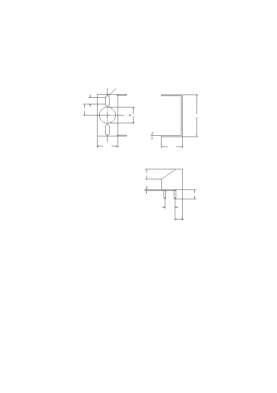
R 1.00
0.5000
10.3000
20.8200
4.9500
0.5000
4.5000
5.0800
3.6450
Clip for SC-2A
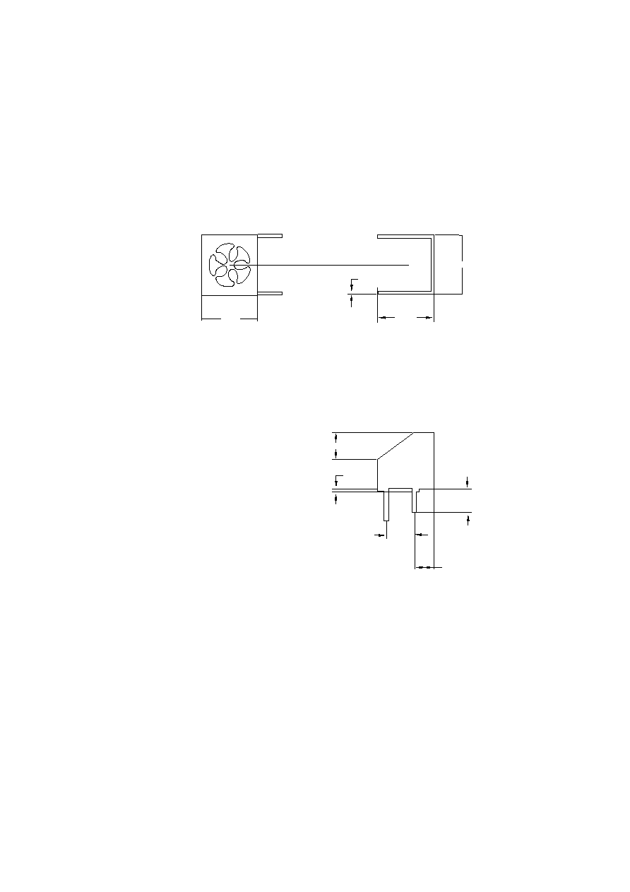
10.25
0.50
10.30
10.70
4.50
3.65
5.08
0.85
0.50
4.95
Clip for Pigtail-3A
PRODUCT INFORMATION
Europe: Tel (46) 8 58 02 45 00
Fax (46) 8 58 02 01 10
Tel (44) 1291 436180
Fax (44) 1291 436771
America: Tel 1-800-96MITEL Fax (613) 592-6909
Asia:
Tel (65) 293 5312
Fax (65) 293 8527
103326 1994-09-20
ST-2A
Package
Emitter or Detector in ST
Æ
Package
Mitel emitters and detectors can be
provided in this low-profile ST
Æ
package. The device is electrically
isolated from the ST
Æ
receptacle to
facilitate electrical connection. And
optimum fiber-coupled power or
responsivity is ensured by active
alignment against the fiber.
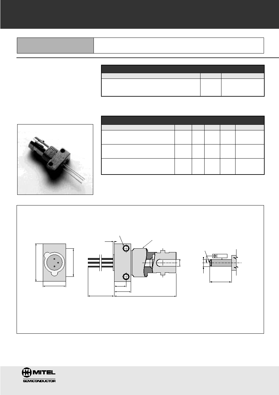
Mechanical Outline of Diode in ST-2A Housing
(ST is a registered trademark of AT&T)
All Dimensions in mm
*
The fiber-coupled power/responsivity is guaranteed to meet the LED/PIN data sheet - provided a ferrule meeting this specification is used.
Absolute Maximum Ratings
Thermal Characteristics
Note 2: Add Rthjc for emitter or detector to estimate the total thermal resistance.
Note 1: Temperature range can be extended to -55∞ to +125∞C on request.
12.7
MARKING SIDE
SLOT SIDE
9.5
7.89
2-56 UNC - 2B
max.0.5
min.12
20.1
3.9
5.4
7.6
3/8"-32 UNEF
0.006
FIBER
END
ÿ2.5
ÿ2.502
+0.01
0
+0
-0.004
MATING FERRULE
*
(not included)
PARAMETER
SYMBOL
LIMIT
Operating & Storage Temperature
Tstg, Top
-40 to + 85 C
ST-2A (Note 1)
PARAMETER
SYMBOL
MIN.
TYP.
MAX.
UNIT
Thermal Resistance - Infinite Heat Sink
Rthcc
40
C/W
(Note 2)
Thermal Resistance - No Heat Sink
Rthca
200
C/W
(Note 2)
Thermal Resistance - On PC Board
Rthca
80
C/W
(Note 2)
PRODUCT INFORMATION
Europe: Tel (46) 8 58 02 45 00
Fax (46) 8 58 02 01 10
Tel (44) 1291 436180
Fax (44) 1291 436771
America: Tel 1-800-96MITEL Fax (613) 592-6909
Asia:
Tel (65) 293 5312
Fax (65) 293 8527
SMA-2A
Package
Emitter or Detector in SMA Package
103325 1994-09-20
Mitel emitters and detectors can be
provided in this low-profile SMA
package. The device is electrically
isolated from the SMA receptacle to
facilitate electrical connection. And
optimum fiber-coupled power or
responsivity is ensured by active
alignment against the fiber.
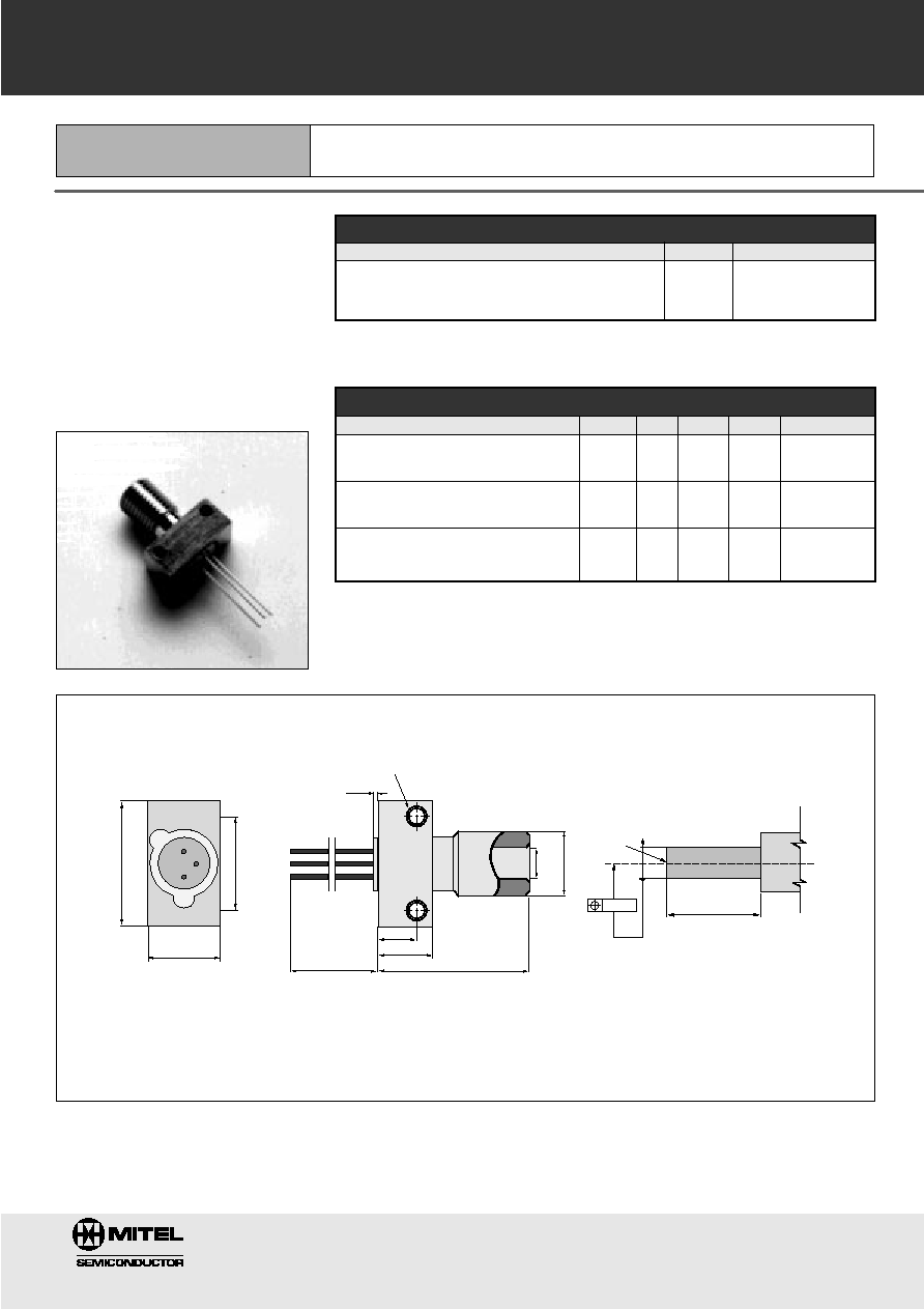
MARKING SIDE
9.5
12.7
max.0.5
2-56 UNC - 2B
3.9
5.7
15.2
min.12
7.2
1/4"-36UNS
ÿ3.176
+0.01
0
9.8 ± 0.03
FIBER
END
0.006
ÿ3.174
+0
-0.004
MATING FERRULE
*
(not included)
Mechanical Outline of Diode in SMA-2A Housing
All Dimensions in mm
*
The fiber-coupled power/responsivity is guaranteed to meet the LED/PIN data sheet - provided a ferrule meeting this specification is used.
Absolute Maximum Ratings
Thermal Characteristics
Note 2: Add Rthjc for emitter or detector to estimate the total thermal resistance.
Note 1: Temperature range can be extended to -55∞ to +125∞C on request.
PARAMETER
SYMBOL
MIN.
TYP.
MAX.
UNIT
Thermal Resistance - Infinite Heat Sink
Rthcc
40
C/W
(Note 2)
Thermal Resistance - No Heat Sink
Rthca
200
C/W
(Note 2)
Thermal Resistance - On PC Board
Rthca
80
C/W
(Note 2)
PARAMETER
SYMBOL
LIMIT
Operating & Storage Temperature
SMA-2A (Note 1)
Tstg, Top
- 40 to +85 C