
Feb.1999
V
µ
A
µ
A
V
MITSUBISHI INSULATED GATE BIPOLAR TRANSISTOR
CT30VM-8
STROBE FLASHER USE
°
V
CES ................................................................................
400V
°
I
CM ....................................................................................
180A
CT30VM-8
450
--
--
--
--
--
--
--
--
10
±
0.1
7.0
I
C
= 1mA, V
GE
= 0V
V
CE
= 400V, V
GE
= 0V
V
GE
=
±
40V, V
CE
= 0V
V
CE
= 10V, I
C
= 1mA
V
(BR)CES
I
CES
I
GES
V
GE(th)
400
±
30
±
40
180
≠40 ~ +150
≠40 ~ +150
V
V
V
A
∞
C
∞
C
V
CES
V
GES
V
GEM
I
CM
T
j
T
stg
10.5MAX.
2.5
2.5
1
0.5
1.5MAX.
1.5MAX.
13.2 ± 0.5
2.6 ± 0.4
4.5
q
w
r
e
0.5
1.3
8.6 ± 0.3
9.8 ± 0.5
q
GATE
w
COLLECTOR
e
EMITTER
r
COLLECTOR
w r
q
e
OUTLINE DRAWING
Dimensions in mm
APPLICATION
Strobe Flasher.
V
GE
= 0V
V
CE
= 0V, See notice 4
V
CE
= 0V, tw = 0.5s
See figure 1
Parameter
Conditions
Symbol
Ratings
Unit
Collector-emitter voltage
Gate-emitter voltage
Peak gate-emitter voltage
Collector current (Pulsed)
Junction temperature
Storage temperature
ELECTRICAL CHARACTERISTICS
(Tj = 25
∞
C)
Symbol
Unit
Parameter
Test conditions
Limits
Min.
Typ.
Max.
MAXIMUM RATINGS
(Tc = 25
∞
C)
Collector-emitter breakdown voltage
Collector-emitter leakage current
Gate-emitter leakage current
Gate-emitter threshold voltage
TO-220C
Feb.1999
RECOMMEND CONDITION
V
CM
= 330V
I
P
= 160A
C
M
= 800
µ
F
V
GE
= 28V
MAXIMUM CONDITION
360V
180A
1000
µ
F
IXe
Vtrig
V
CE
R
G
V
G
IGBT
C
M
+
V
CM
Vtrig
V
G
Ixe
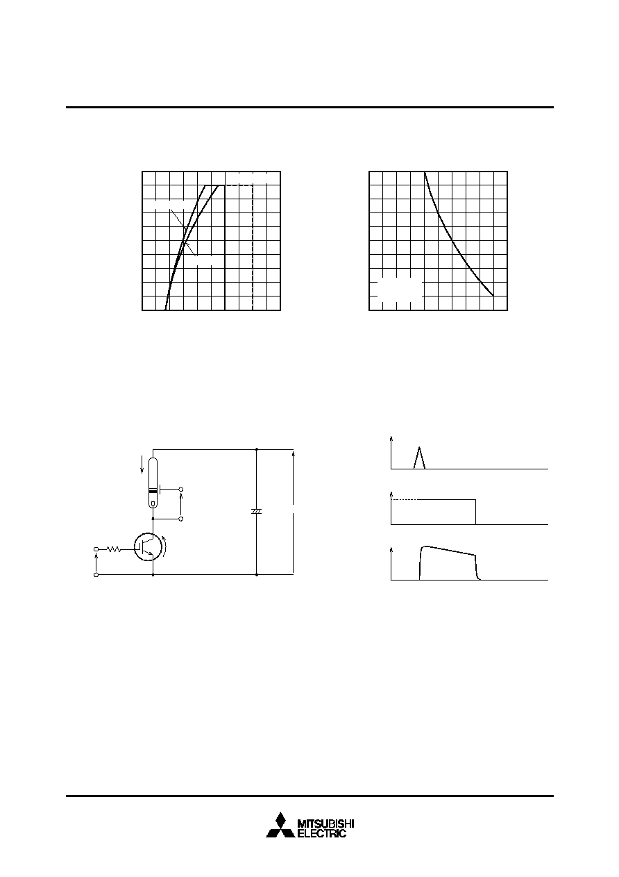
2000
1600
1200
800
400
0
220
200
180
140
120
160
V
CM
= 350V
<
T
C
=
70∞C
V
GE
=
28V
>
200
160
120
80
40
0
50
40
30
10
0
20
<
T
C
=
50∞C
<
T
C
=
70∞C
C
M
= 1000
µ
F
≠
MAXIMUM PULSE COLLECTOR CURRENT
PULSE COLLECTOR CURRENT I
CP
(A)
MAIN CAPACITOR C
M
(
µ
F)
MAXIMUM PULSE COLLECTOR CURRENT
GATE-EMITTER VOLTAGE V
GE
(V)
PULSE COLLECTOR CURRENT I
CM
(A)
TRIGGER
SIGNAL
Xe TUBE
CURRENT
VOLTAGE
IGBT GATE
MITSUBISHI INSULATED GATE BIPOLAR TRANSISTOR
CT30VM-8
STROBE FLASHER USE
PERFORMANCE CURVES
APPLICATION EXAMPLE
Notice 1. Gate drive voltage during on-period must be applied to satisfy the rating of maximum pulse collector current.
And reverse gate current during turn-off must be kept less than 1A.
(In general, it is satisfied if R
G
30
)
Notice 2. IGBT has MOS structure and its gate is insulated by thin silicon oxide.
So please handle carefully not to suffer from electrostatic charge.
Notice 3. The operation life should be endured 5,000 shots under the charge current
(I
xe
180A : full luminescence condition) of main condenser (C
M
=1000
µ
F).
Repetition period under full luminescence condition is over 3 seconds.
Notice 4. Total operation hours must be applied within 5,000 hours.
Figure 1
Figure 2