
MITSUMI
No-adjustment Sync Separator MM1108
No-adjustment Sync Separator
Monolithic IC MM1108
Outline
This IC is a no-adjustment sync separator IC designed for use in VCR, TV and other video equipment.
Features
1. Low current consumption
4.4mA typ.
2. Open collector output
3. Built-in 3V regulator handles power supply ripple
4. Built-in capacitor for vertical sync separation
5. Time from vertical signal to H. SYNC output re-sync reduced (relative to LVA519)
6. Supports both PAL and NTSC formats
7. Sync separation level can be adjusted with external constants
Package
SOP-8C (MM1108XF)
SIP-8A (MM1108XS)
DIP-8B (MM1108XD)
Applications
1. TV
2. VCR
3. VCR with camera
Block Diagram
MITSUMI
No-adjustment Sync Separator MM1108
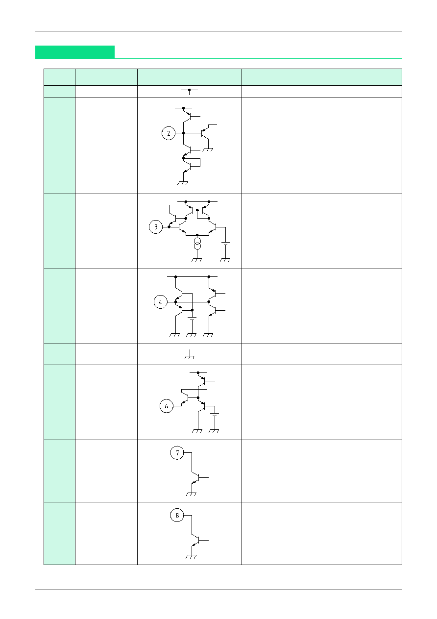
Pin Description
Pin no.
Pin name
Internal equivalent circuit diagram
Function
1
V
CC
Power supply voltage pin. Impresses 5V.
2
SC
VCO integration pin
Free run frequency determined by external
capacitor between Pin 2 and GND, and
external resistor between Pin 3 and GND.
3
VCO
VCO input pin
Pin 4 output is input via external loop filter.
4
LPF
Phase comparator output pin.
5
GND
GND
6
V
IN
Signal input pin
Inputs video signal.
7
V.SYNC
V. SYNC output pin
Outputs vertical sync signal separated from
input video signal.
8
H.SYNC
H. SYNC output pin
Outputs horizontal sync signal synchronized
to input video signal, except for vertical
feedback interval. For no signal, outputs
free run frequency horizontal sync signal.

MITSUMI
No-adjustment Sync Separator MM1108
Absolute Maximum Ratings
(Ta=25�C)
Item
Symbol
Ratings
Units
Storage temperature
T
STG
-40~+125
�C
Operating temperature
T
OPR
-20~+75
�C
Power supply voltage
V
CC
max.
7
V
Allowable loss
Pd
300
*
mW
Item
Symbol
Measurement
Measurement conditions
Min. Typ. Max. Units
circuit
Operating power supply voltage
V
CC
V
CC
4.5
5.0
5.5
V
Consumption current
Id
Id
SW1 : b
4.4
7.0
mA
Minimum sync separation
I
SEPA
I
IN
SW1 : c, VR1 : H L
*
1
15
30
60
uA
operating current
Free-running frequency
f
O
TP1
SW1 : b
14.7 15.7 16.7 kHz
Horizontal sync signal
f
CAP
TP1
V
IN
: signal 1, 15.73kHz
acquisition range
SW2 : b
*
2
*
3
2.1
2.7
kHz
H. sync pulse width
t
W
1
TP1
V
IN
: signal 1, 15.73kHz
*
4
4.3
4.7
5.1
uS
H. sync delay time
t
d
1
TP1
V
IN
: signal 1, 15.73kHz
*
4
-0.3
0.2
0.7
uS
H. sync output voltage L
V
L
1
TP1
V
IN
: signal 1 ,15.73kHz
*
4
0.2
0.4
V
H. sync output voltage H
V
H
1
TP1
V
IN
: signal 1, 15.73kHz
*
4
4.8
5.0
V
V. sync pulse width
t
W
2
TP2
V
IN
: staircase wave 1V
P-P
*
5
140
200
260
uS
V. sync delay time
t
d
2
TP2
V
IN
: staircase wave 1V
P-P
*
5
6.0
10.0 20.0
uS
V. sync output voltage L
V
L
2
TP2
V
IN
: staircase wave 1V
P-P
*
5
0.2
0.4
V
V. sync output voltage H
V
H
2
TP2
V
IN
: staircase wave 1V
P-P
*
5
4.8
5.0
V
Electrical Characteristics
(Except where noted otherwise, Ta=25�C, V
CC
=5.0V, SW1=a, SW2=a)
Notes :
*
1 Minimum sync separation operating current measurement
Given SW1 : c, change VR1 from high to low, and measure current flowing on I
IN
when TP2
output switches from high to low.
*
2 Signal 1 : Rectangular wave signal with 0.3V amplitude and pulse width 4.7�S
*
3 Measuring horizontal sync signal pull-in range
Given SW1 : a and SW2 : b, with TP1 waveform not synchronized to signal 1, adjust VR2 so that
they are synchronized. Next, switch SW1 to b, and measure TP1 output free run frequency. The
horizontal signal pull-in range is the smaller of the measured value and the difference from
15.73kHz.
4.7uS
Signal 1 waveform
*
Package : SOP-8C

MITSUMI
No-adjustment Sync Separator MM1108
*
4
H. SYNC measurement
*
5
V. SYNC measurement
t
w
2
t
d
2
V
H
2
V
L
2
Input video signal
(Horizontal sync
signal portion)
TP2 waveform
Measuring Circuit
t
w
1
t
d
1
V
H
1
V
L
1
Signal 1
TP1 waveform

MITSUMI
No-adjustment Sync Separator MM1108
Application Circuits
Application Circuit 1
Application Circuit 2