 | –≠–ª–µ–∫—Ç—Ä–æ–Ω–Ω—ã–π –∫–æ–º–ø–æ–Ω–µ–Ω—Ç: MS6713 | –°–∫–∞—á–∞—Ç—å:  PDF PDF  ZIP ZIP |
Document Outline
- ˛ˇ
- ˛ˇ
- ˛ˇ
- ˛ˇ
- ˛ˇ
- ˛ˇ
- ˛ˇ
- ˛ˇ
- ˛ˇ
- ˛ˇ
- ˛ˇ
- ˛ˇ
- ˛ˇ
- ˛ˇ
- ˛ˇ
- ˛ˇ

MO
SA
MS6713
3 Stereo Inputs / 4 Channels Output Audio Processor
REV1.0 1 www.mosanalog.com
3 Stereo Inputs and 4 Channels Output
Volume, Tone, Balance, Fader, Loudness,
and Selectable Input Gain
FEATURES
Operation range : 2.7V~5V
3 stereo inputs with selectable input gain
4 independent speaker controls for fader and balance
Tone controls (treble and bass) and loudness function
Independent mute function
Volume control in 1.25 dB/step
I
2
C interface
Components less and good PSRR
Housed in SOP28, SSOP28 packages
APPLICATIONS
Portable audio device
Car stereo audio
Hi-Fi audio system
Cross-reference:
TDA7313, PT2313 (for SOP28 version)
DESCRIPTION
The MS6713 is a 3 stereo inputs/4-channel outputs digital control audio processor for the low voltage operation.
Volume, tone (bass and treble), balance (left/right), and fader (front/rear) processor are incorporated into a single chip.
The MS6713 also has the loudness function and selectable input gain. These functions can be built a Hi-Fi audio
system easily. All functions are programmable via the serial I
2
C bus. The default states of the chip as the power is on
are: the volume is -78.75dB, the stereo 4 is selected, all the speakers are mute and the gains of the input stage, the bass
and the treble are 0dB. The stereo 4 is connected internally, but not available on pins.
BLOCK DIAGRAM
RIN2
RIN1
Treble
Bass
Volume &
Londness
Volume &
Londness
Bass
Treble
LIN1
LIN2
LIN3
RIN3
REF
R
B
R
B
Input
Selector
&Gain
Control
LOUD_R
ROUT
RIN
TREB_R
BOUT_R BIN_R
LOUD_L
LOUT
LIN
TREB_L
BOUT_L BIN_L
1
7
8
9
4
5
6
13
14
15
10
11
12
19
20
21
16
17
18
Speak
ATT
Mute
Speak
ATT
Mute
Speak
ATT
Mute
Speak
ATT
Mute
OUT_LF
OUT_LR
OUT_RF
OUT_RR
25
22
23
24
SCL
SDA
DGND
26
27
28
Supply
AVDD AGND
2
3
Serial Bus Decoder and Latches

MO
SA
MS6713
3 Stereo Inputs / 4 Channels Output Audio Processor
REV1.0 2 www.mosanalog.com
PIN CONFIGURATION
Symbol
Pin
Description
REF 1
Analog Reference Voltage1/2VDD
VDD
2
Supply Input Voltage
AGND 3
Analog
Ground
TREB_L
4
Left Channel Input for Treble Controller
TREB_R
5
Right Channel Input for Treble Controller
RIN
6
Audio Processor Right Channel Input
ROUT
7
Gain Output and Input Selector for Right Channel
LOUD_R
8
Right Channel Loudness Input
RIN3
9
Right Channel Input 3
RIN2
10
Right Channel Input 2
RIN1
11
Right Channel Input 1
LOUD_L
12
Left Channel Loudness Input
LIN3
13
Left Channel Input 3
LIN2
14
Left Channel Input 2
LIN1
15
Left Channel Input 1
LIN
16
Audio Processor Left Channel Input
LOUT
17
Gain Output and Input Selector for Left Channel
BIN_L
18
Left Bass Controller Input Channel
BOUT_L
19
Left Bass Controller Output Channel
BIN_R
20
Right Bass Controller Input Channel
BOUT_R
21
Right Bass Controller Output Channel
OUT_RR
22
Right Rear Speaker Output
OUT_LR
23
Left Rear Speaker Output
OUT_RF
24
Right Front Speaker Output
OUT_LF
25
Left Front Speaker Output
DGND 26
Digital
Ground
SDA 27
I
2
C Data Input
SCL 28
I
2
C Clock Input
BIN_L
LOUT
LIN
LIN1
LIN2
LIN3
LOUD_L
RIN1
27
26
25
28
2
3
4
1
SCL
SDA
DGND
OUT_LF
REF
VDD
AGND
TREB_L
OUT_RF
OUT_LR
OUT_RR
BOUT_R
BIN_R
BOUT_L
RIN2
RIN3
LOUD_R
ROUT
RIN
TREB_R
23
22
21
24
6
7
8
5
19
18
17
20
10
11
12
9
15
16
14
MS6713
13
SOP28 / SSOP28
MO
SA
MS6713
3 Stereo Inputs / 4 Channels Output Audio Processor
REV1.0 3 www.mosanalog.com
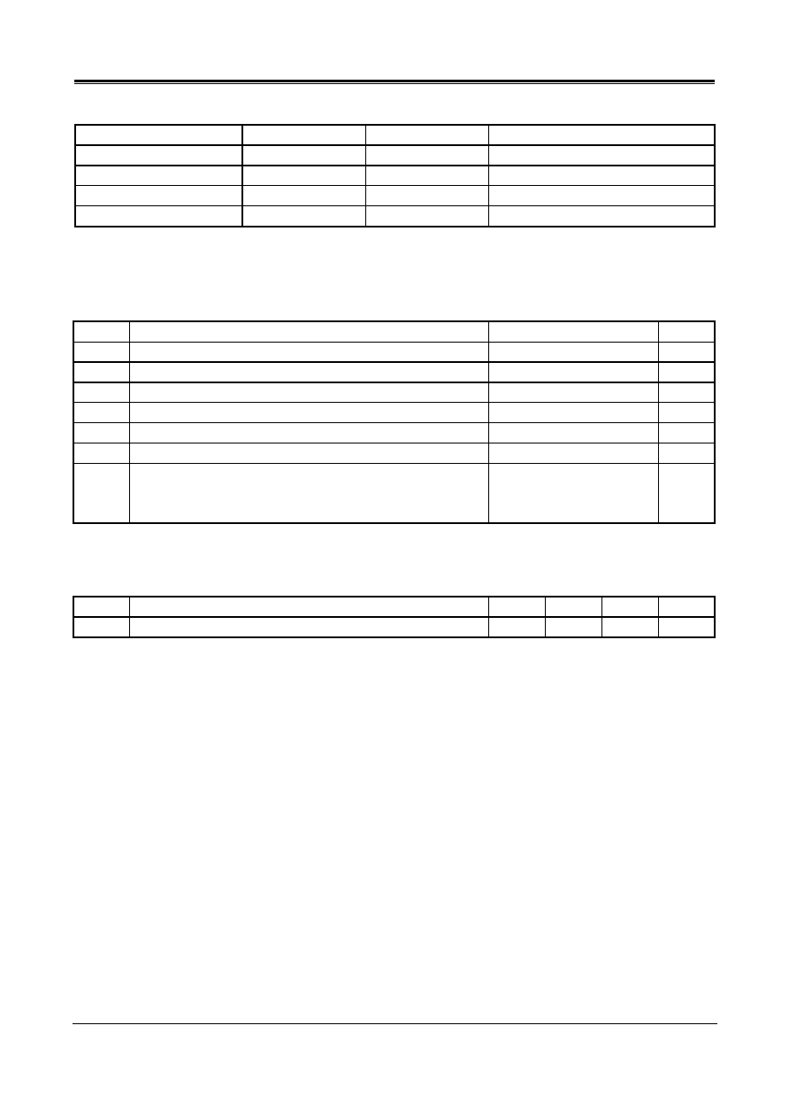
ORDERING INFORMATION
Package Part
number
Packaging Marking
Transport Media
28-Pin SOP (lead free)
MS6713GTR
MS6713G
1k Units Tape and Reel
28-Pin SOP (lead free)
MS6713GU
MS6713G
25 Units Tube
28-Pin SSOP (lead free)
MS6713SSGTR
MS6713G
2.5k Units Tape and Reel
28-Pin SSOP (lead free)
MS6713SSGU
MS6713G
50 Units Tube
ABSOLUTE MAXIMUM RATINGS
Symbol
Parameter Rating
Unit
V
DD
Supply
Voltage
6
V
V
ESD
Electrostatic Handling
-3000 to 3000
V
T
STG
Storage Temperature Range
-65 to 150
T
A
Operating Ambient Temperature Range
-40 to 85
T
J
Maximum Junction Temperature
150
T
S
Soldering Temperature, 10 seconds
260
R
THJA
Thermal Resistance from Junction to Ambient in Free Air
SOP28
SSOP28
210
210
/W
OPERATING RATINGS
Symbol Parameter Min Typ Max Unit
V
DD
Supply
Voltage
2.7 - 5.5 V
MO
SA
MS6713
3 Stereo Inputs / 4 Channels Output Audio Processor
REV1.0 4 www.mosanalog.com
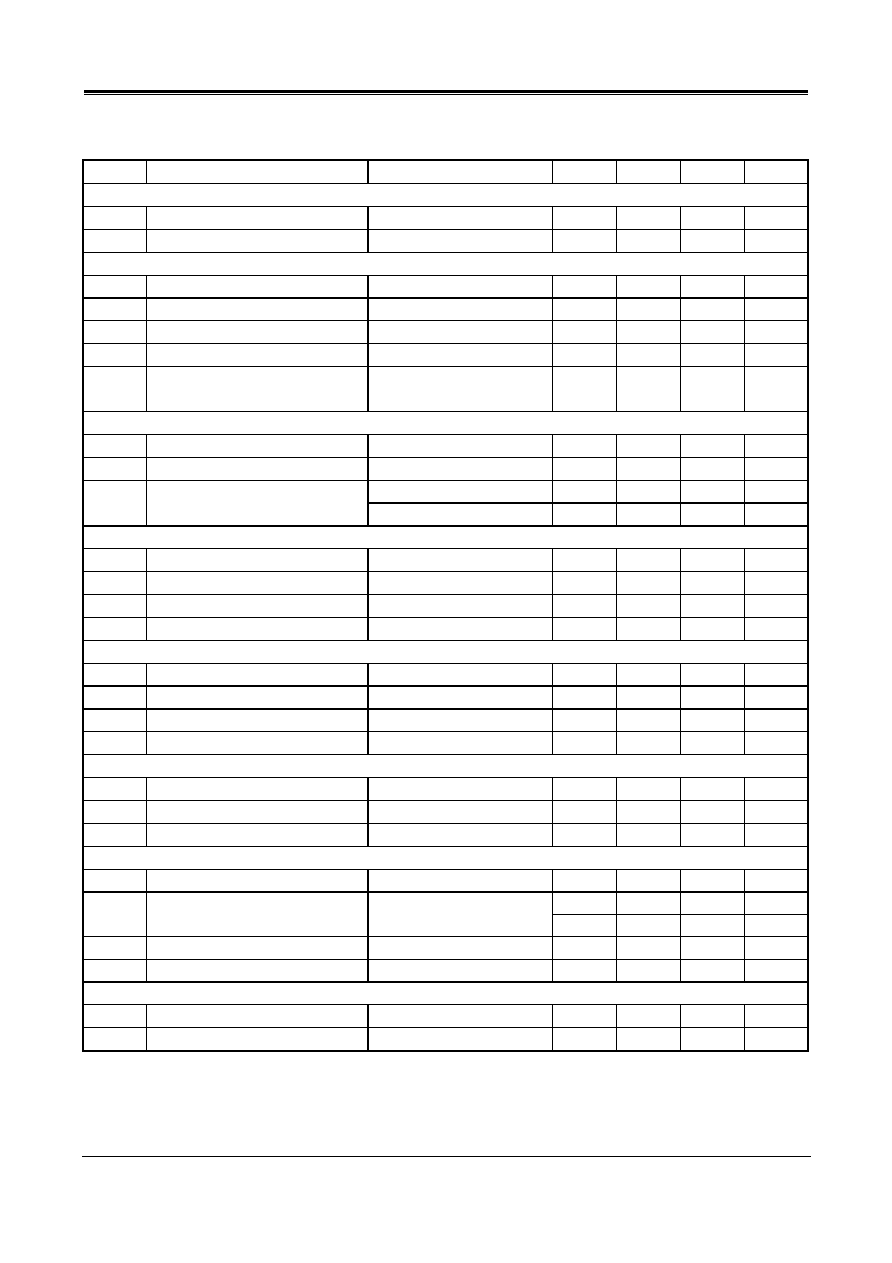
5V ELECTRICAL CHARACTERISTICS
(Ta=25, All stages 0dB, f=1kHz, C
REF
=22uF, refer to the application circuit; unless otherwise specified)
Symbol Parameter
Conditions Min
Typ
Max
Unit
Supply
I
Q
Quiescent Current
V
IN
=0V -
12.2
12.5
mA
PSRR
Power Supply Rejection Ratio
C
REF
= 22uF, f = 100Hz
55
60
-
dB
Input Selectors
R
IN
Input Resistance
Input 1,2,3
35
50
70
k
G
IN
Input Gain Range
Gain
0
-
11.25
dB
G
STEP
Step
Resolution
- 3.75 - dB
ERR
G
Gain Setting error
-0.2
0
0.2
dB
LOUD Loudness
C
Loud
=100nF, f =20Hz
Volume=-40dB
19 20 - dB
Volume control
CR
VOL
Volume Control Range
Attenuation
-78.75
-
0
dB
RES
VOL
Volume Step Resolution
-
1.25
-
dB
Av = 0 to -40dB
-1
0
0.5
dB
ERR
VOL
Volume Setting Error
Av = -40 to -60dB
-5
0
1
dB
Speaker Attenuators
CR
SPK
Speaker Control Range
Attenuation
-37.5
-
0
dB
RES
SPK
Speaker
Step
Resolution
- 1.25 - dB
ERR
SPK
Speaker Setting Error
-0.2
0
0.1
dB
MUTE Output
Mute
Attenuation
-
-65
-60
dB
Bass Control
CR
BAS
Bass Control Range
Boost/Cut
-14
-
14
dB
RES
BAS
Bass Step Resolution
-
2
-
dB
ERR
BAS
Speaker Setting Error
f =100Hz
-0.3
0
0.1
dB
R
B
B
Internal Feedback Resistance
34
44
58
k
Treble Control
CR
BAS
Treble Control Range
Boost/Cut
-14
-
14
dB
RES
BAS
Treble Step Resolution
-
2
-
dB
ERR
BAS
Treble Setting Error
f =20kHz
-0.3
0
0.1
dB
General
VO
MAX
Maximum Output Voltage Swing (THD+N)/S <0.3%
-
4.5
-
Vpp
- -75 - dB
THD+N
Total Harmonic Distortion Plus
Noise
V
OUT
=2Vpp
- 0.0177 - %
S/N Signal-to-Noise
Ratio
V
OUT
=4Vpp -
97
-
dB
CS
Channel Separation Left/Right
93
97
-
dB
Bus Input
V
IH
Bus High Input Level
2
-
-
V
V
IL
Bus Low Input Level
-
-
0.8
V
Notes:
Bass and Treble response see to curve. The center frequency and quality of the response behavior can be chosen by the
external.

MO
SA
MS6713
3 Stereo Inputs / 4 Channels Output Audio Processor
REV1.0 5 www.mosanalog.com
2.7V ELECTRICAL CHARACTERISTICS
(Ta=25, All stages 0dB, f=1kHz, C
REF
=22uF, refer to the application circuit; unless otherwise specified)
Symbol Parameter
Conditions Min
Typ
Max
Unit
Supply
I
Q
Quiescent Current
V
IN
=0V -
8.7
9
mA
PSRR
Power Supply Rejection Ratio
C
REF
= 22uF, f = 100Hz
53
58
-
dB
General
VO
MAX
Maximum Output Voltage Swing (THD+N)/S <0.3%
-
2.5
-
Vpp
- -50 - dB
THD+N
Total Harmonic Distortion Plus
Noise
V
OUT
=2Vpp
- 0.3 - %
S/N Signal-to-Noise
Ratio
V
OUT
=2.5Vpp 90
94
-
dB
CS
Channel Separation Left/Right
90
94
-
dB
TYPICAL PERFORMANCE CHARACTERISTICS
(Ta=25, All stages 0dB, f=1kHz, C
REF
=22uF, refer to the application circuit; unless otherwise specified)
Lou
d
(
d
B)
FREQUENCY (Hz)
Lou
d
(
d
B)
FREQUENCY (Hz)
Lou
d
(
d
B)
FREQUENCY (Hz)
Loudness vs. Volume
V
DD
=5V
Volume=-40dB
V
DD
=5V
100nF
33nF
OPEN
10nF
220nF
Loudness OFF
56nF
V
DD
=5V
C
LOUD
= 100nF
Loudness vs. Frequency vs. Volume
Loudness vs. External Capacitors
Tone (
d
B)
FREQUENCY (Hz)
C
H
AN
N
EL SEP
AR
ATI
O
N
(
d
B)
FREQUENCY (Hz)
QUIE
S
C
E
N
T CURRE
NT (mA
)
SUPPLY VOLTAGE (V)
V
DD
=2.7V
V
IN
=-3dBV
V
DD
=5V
V
IN
=0dBV
V
DD
=5V
Treble=Bass= -14~14dB
Typical Tone Response
Channel Separation vs. Frequency
Quiescent Current vs. Supply Voltage