
1
Rev. 1.0 February 1998
MOSEL VITELIC
MSU2052/U2032
Features
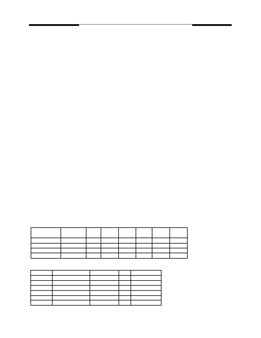
Postfix
bla nk
P
J
Q
U
Pa ck age
d ice
4 0L P DIP
4 4L P LCC
4 4L P QFP
4 4L L QFP
P in/Pa d
Configura tion
p ag e 18
pa ge 2
pa ge 2
pa ge 2
pa ge 2
Dime ns ion
p ag e 18
p ag e 14
p ag e 15
p ag e 16
p ag e 17
L ogo Siz e at
Top Ma r ki ng
-
5 .0 x 4 .2 mm
4 .5 x 3 .8 mm
2 .8 x 2 .4 mm
2 .8 x 2 .4 mm
M.V.I.
W.B.
Philips
L.G.
Intel
CCL. itri
Atmel
MSU2052
W78C52
80C52
G MS80C502
80C52
CIC80520
AT80C52
MSU2032
W78C32
80C32
G MS80C302
80C32
- - - - -
AT80C32
Cross Reference
Specifications subject to change without notice, contact your sales representatives for the most recent information.
Working voltage : L series at 2.7V through 4.5V
while S & C series at 4.5 V through 5.5 V
General 80C51 family compatible
64 K byte External Memory Space
8 K byte ROM
256 byte data RAM
Three 16 bit Timers/Counters
Four 8-bit I/O ports
Full duplex serial channel
Bit operation instructions
Page free jumps
8 - bit Unsigned Division
8 - bit Unsigned Multiply
BCD arithmatic
Direct Addressing
Indirect Addressing
Nested Interrupt
Two priority level interrupt
A serial I/O port
Power save modes:
Idle mode and Power down mode
Working at 16/25/40 MHz Clock
Description
The MVI MSU2052 series product is an 8 - bit
single chip microcontroller. It provides hardware
features and a powerful instruction set, neces-
sary to make it a versatile and cost effective
controller for those applications demand up to
32 I/O pins or need up to 64 K byte external
memory either for program or for data or mixed.
A serial input / output port is provided for I/O
expansion, Inter - processor communications,
and full duplex UART.
Ordering Information
MSU2032ihhk
MSU2052ihh - yyyk
i: process identifier {L, C}.
hh: working clock in MHz {16, 25, 40}.
yyy: production code {001, ..., 999}
k: package type postfix {as below table}.
Product List
MSU2032L16
, low working voltage 16 MHz ROM less MCU
MSU2032C16
, 16 MHz ROM less MCU
MSU2032C25
, 25 MHz ROM less MCU
MSU2032C40
, 40 MHz ROM less MCU
MSU2052L16
, low working voltage 16 MHz 4 KB internal ROM MCU
MSU2052C16
, 16 MHz 4 KB internal ROM MCU
MSU2052C25
, 25 MHz 4 KB internal ROM MCU
MSU2052C40
, 40 MHz 4 KB internal ROM MCU

2
Rev. 1.0 February 1998
MOSEL VITELIC
MSU2052/U2032
1
2
3
4
5
6
7
8
9
10
11
12
13
14
15
16
17
18
19
20
40
39
38
37
36
35
34
33
32
31
30
29
28
27
26
25
24
23
22
21
T2EX/P1.0
T2/P1.1
P1.2
P1.3
P1.4
P1.5
P1.6
P1.7
RES
RXD/P3.0
TXD/P3.1
#INT0/P3.2
#INT1/P3.3
T0/P3.4
T1/P3.5
#WR/P3.6
#RD/P3.7
XTAL2
XTAL1
VSS
VDD
AD0/P0.0
AD1/P0.1
AD2/P0.2
AD3/P0.3
AD4/P0.4
AD5/P0.5
AD6/P0.6
AD7/P0.7
#EA
ALE
#PSEN
A15/P2.7
A14/P2.6
A13/P2.5
A12/P2.4
A11/P2.3
A10/P2.2
A9/P2.1
A8/P2.0
MSU2032ihhP, MSU2052ihh-
yyyP
(Top View)
40L PDIP
MSU2032ihhQ,
MSU2052ihh-
yyyQ
44L PQFP
(Top View)
AD4/P 0.4
AD5/P 0.5
AD6/P 0.6
AD7/P 0.7
#EA
NC
ALE
#PSEN
A15/P 2.7
A14/P 2.6
A13/P 2.5
P 1.5
P 1.6
P 1.7
RES
RXD/P 3.0
NC
TXD/P 3.1
#INT0/P 3.2
#INT1/P 3.3
T0/P 3.4
T1/P 3.5
P 1.4
P 1.3
P 1.2
T2EX/P 1.1
T2/P 1.0
NC
VDD
AD0/P 0.0
AD1/P 0.1
AD2/P 0.2
AD3/P 0.3
#WR/P 3.6
#RD/P 3.7
XTAL2
XTAL1
VSS
NC
A8/P 2.0
A9/P 2.1
A10/P 2.2
A11/P 2.3
A12/P 2.4
1
2
3
4
5
6
7
8
9
10
11
33
32
31
30
29
28
27
26
25
24
23
12 13 14 15 16 17 18 19 20 21 22
44 43 42 41 40 41 40 39 38 37 34
MSU2032ihhU,
MSU2052ihh-
yyyU
44L LQFP
(Top View)
AD4/P 0.4
AD5/P 0.5
AD6/P 0.6
AD7/P 0.7
#EA
NC
ALE
#PSEN
A15/P 2.7
A14/P 2.6
A13/P 2.5
P 1.5
P 1.6
P 1.7
RES
RXD/P 3.0
NC
TXD/P 3.1
#INT0/P 3.2
#INT1/P 3.3
T0/P 3.4
T1/P 3.5
P 1.4
P 1.3
P 1.2
T2EX/P 1.1
T2/P 1.0
NC
VDD
AD0/P 0.0
AD1/P 0.1
AD2/P 0.2
AD3/P 0.3
#WR/P 3.6
#RD/P 3.7
XTAL2
XTAL1
VSS
NC
A8/P 2.0
A9/P 2.1
A10/P 2.2
A11/P 2.3
A12/P 2.4
1
2
3
4
5
6
7
8
9
10
11
33
32
31
30
29
28
27
26
25
24
23
12 13 14 15 16 17 18 19 20 21 22
44 43 42 41 40 41 40 39 38 37 34
MSU2032ihhJ,
MSU2052ihh-
yyyJ
44L PLCC
(Top View)
AD4/P 0.4
AD5/P 0.5
AD6/P 0.6
AD7/P 0.7
#EA
NC
ALE
#PSEN
A15/P 2.7
A14/P 2.6
A13/P 2.5
P 1.5
P 1.6
P 1.7
RES
RXD/P 3.0
NC
TXD/P 3.1
#INT0/P 3.2
#INT1/P 3.3
T0/P 3.4
T1/P 3.5
P 1.4
P 1.3
P 1.2
T2EX/P 1.1
T2/P 1.0
NC
VDD
AD0/P 0.0
AD1/P 0.1
AD2/P 0.2
AD3/P 0.3
#WR/P 3.6
#RD/P 3.7
XTAL2
XTAL1
VSS
NC
A8/P 2.0
A9/P 2.1
A10/P 2.2
A11/P 2.3
A12/P 2.4
7
8
9
10
11
12
13
14
15
16
17
39
38
37
36
35
34
33
32
31
30
29
18 19 20 21 22 23 24 25 26 27 28
6 5 4 3 2 1 44 43 42 41 40
Pin Configurations

3
Rev. 1.0 February 1998
MOSEL VITELIC
MSU2052/U2032
Block Diagram
RES
Vdd
Vss
XTAL2
XTAL1
#EA
#PSEN
ALE
Timer 1
Timer 0
Decoder &
Register
256 bytes
RAM
8K bytes
ROM
Register
Program
Counter
PC
Increamenter
Buffer
DPTR
Stack
Pointer
Port 3
Latch
Port 1
Latch
Port 2
Latch
Port 0
Latch
Port 0
Driver
Port 2
Driver
Port 1
Driver
Port 3
Driver
8
8
8
8
Reset
Circuit
Power
Circuit
Interrupt
Circuit
Timming
Generator
to pertinent blocks
to whole chip
to pertinent blocks
to whole system
Acc
Buffer1
Buffer2
ALU
PSW
Instruction
Register
Timer 2

4
Rev. 1.0 February 1998
MOSEL VITELIC
MSU2052/U2032
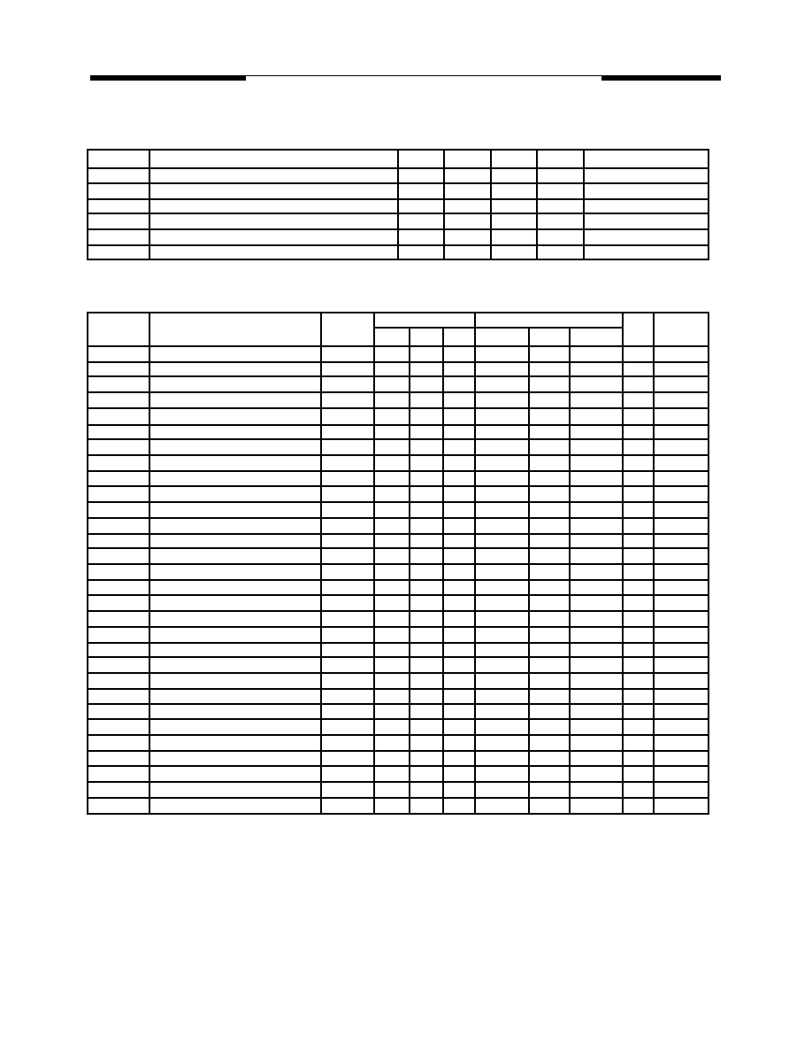
40 PDIP
Pin#
1
2
3
4
5
6
7
8
9
10
11
12
13
14
15
16
17
18
19
20
21
22
23
24
25
26
27
28
29
30
31
32
33
34
35
36
37
38
39
40
Dice
Pad#
39
40
41
42
43
1
2
3
4
5
6
7
8
9
10
11
12
13
14
15~17
18
19
20
21
22
23
24
25
26
27
28
29
30
31
32
33
34
35
36
37,38
44 PLCC
Pin#
2
3
4
5
6
7
8
9
10
11
13
14
15
16
17
18
19
20
21
22
24
25
26
27
28
29
30
31
32
33
35
36
37
38
39
40
41
42
43
44
Symbol
T2EX/P1.0
T2/P1.1
P1.2
P1.3
P1.4
P1.5
P1.6
P1.7
RES
RXD/P3.0
TXD/P3.1
#INT0/P3.2
#INT1/P3.3
T0/P3.4
T1/P3.5
#WR/P3.6
#RD/P3.7
XTAL2
XTAL1
VSS
A8/P2.0
A9/P2.1
A10/P2.2
A11/P2.3
A12/P2.4
A13/P2.5
A14/P2.6
A15/P2.7
#PSEN
ALE
#EA
AD7/P0.7
AD6/P0.6
AD5/P0.5
AD4/P0.4
AD3/P0.3
AD2/P0.2
AD1/P0.1
AD0/P0.0
VDD
Active
L/-
L/-
L/-
L/-
L
H
L
I/O
i/o
i/o
i/o
i/o
i/o
i/o
i/o
i/o
i
i/o
i/o
i/o
i/o
i/o
i/o
i/o
i/o
o
i
i/o
i/o
i/o
i/o
i/o
i/o
i/o
i/o
o
o
i
i/o
i/o
i/o
i/o
i/o
i/o
i/o
i/o
Names
bit 0 of Port 1 & timer 2
bit 1 of Port 1 & timer control
bit 2 of Port 1
bit 3 of Port 1
bit 4 of Port 1
bit 5 of Port 1
bit 6 of Port 1
bit 7 of Port 1
Reset
bit 0 of Port 3 & Receive data
bit 1 of Port 3 & Transmit data
bit 2 of Port 3 & low true Interrupt 0
bit 3 of Port 3 & low true Interrupt 1
bit 4 of Port 3 & Timer 0
bit 5 of Port 3 & Timer 1
bit 6 of Port 3 & Write (low enable)
bit 7 of Port 3 & Read (low enable)
Crystal out
Crystal in
Sink Voltage, Ground
bit 0 of Port 2 & Address 8
bit 1 of Port 2 & Address 9
bit 2 of Port 2 & Address 10
bit 3 of Port 2 & Address 11
bit 4 of Port 2 & Address 12
bit 5 of Port 2 & Address 13
bit 6 of Port 2 & Address 14
bit 7 of Port 2 & Address 15
Program store enable (low enable)
Address latch enable
External access first 8 KB memory
bit 7 of Port 0 & Address or Data 7
bit 6 of Port 0 & Address or Data 6
bit 5 of Port 0 & Address or Data 5
bit 4 of Port 0 & Address or Data 4
bit 3 of Port 0 & Address or Data 3
bit 2 of Port 0 & Address or Data 2
bit 1 of Port 0 & Address or Data 1
bit 0 of Port 0 & Address or Data 0
Drive Voltage, +3 Vcc (or +5 Vcc)
44 LQFP
Pin#
40
41
42
43
44
1
2
3
4
5
7
8
9
10
11
12
13
14
15
16
18
19
20
21
22
23
24
25
26
27
29
30
31
32
33
34
35
36
37
38
44 PQFP
Pin#
40
41
42
43
44
1
2
3
4
5
7
8
9
10
11
12
13
14
15
16
18
19
20
21
22
23
24
25
26
27
29
30
31
32
33
34
35
36
37
38
Pin Descriptions

5
Rev. 1.0 February 1998
MOSEL VITELIC
MSU2052/U2032
Pin Descriptions
Vss
Circuit ground potential.
VDD
+3V (or +5 V) power supply during operation.
PORT 0
Port 0 is an 8-bit open drain bidirectional I/O port.
It is also the multiplexed low-order address and data
bus when using external memory.
It also contains the timer 2 & its control pins.
PORT 1
Port 1 is an 8-bit quasi-bidirectional I/O port with
internal pull-up resistance.
PORT 2
Port 2 is an 8-bit quasi-bidirectional I/O port with
internal pull-up resistance. It also emit the high-order
address byte when accessing external memory.
PORT 3
Port 3 is an 8-bit quasi-bidirectinal I/O port with internal
pull-up resistance. It also contains the interrupt, timer,
serial port and #RD as well as #WR pins that are used
by various options. The output latch corresponding to a
secondary function must be programmed to one (1) for
that function to operate. The secondary functions are
assigned to the pins of port 3, as follows:
- RXD/data (P3.0). Serial port's transmitter data output
(asynchronous) or data input/output (asynchronous).
- TXD/clock (P3.1). Serial port's transmitter data
output (asynchronous) or data output (asynchronous).
- #INT0 (P3.2). Interrupt 0 input or gate control input
for counter 0.
- #INT1 (P3.3). Interrupt 1 input or gate control input
for counter 1.
- T0 (P3.4). Input to counter 0.
- T1 (P3.4). Input to counter 1.
- #WR (P3.6). The write control signal latches the data
byte from Port 0 into the External Data Memory.
- #RD (P3.7). The read control signal enables External
Data Memory to Port 0.
RES
A high on this pin for two machine cycles (24 clocks)
while the oscillator is running, resets the device. The
data in RAM is preserved when reset signals - reset
does not clear the data in RAM.
ALE
Provides Address Latch Enable output used for latching
the address into external memory during normal
operation.
#PSEN
The Program Store Enable output is a control signal
that enables the external Program Memory to the bus
during normal fetch operations.
#EA
When held at a TTL high level, the MSU2052 executes
instructions from the internal ROM when the PC is less
than 4096. When held at a TTL low level, the
MSU2052 fetches all instuctions from external Program
Memory.
XTAL 1
Input to the oscillator's high gain amplifier. A crystal or
external source can be used.
XTAL 2
Output from the oscillator's amplifier. Required when a
crystal is used.
Terms
Idle Mode
During idle mode, the CPU is stopped but below blocks
are kept functioning: clock generator, RAM, timer/
counters, serial port and interrupt block. To save power
consumption, user's software program can invoke this
mode. The on-chip data RAM retains the values during
this mode, but the processor stops executing
instructions. In Idle mode (IDL=1), the oscillator
continues to run and the interrput, and timer blocks
continue to be clocked but the clock signal is gated off
to the CPU. The activities of the CPU no longer exist
unless waiting for an interrupt request.
-An instruction that sets flag (PCON.0) causes that to be
the last instruction executed before going into the Idle
Mode.
-In the Idle Mode, the internal clock signal is gated off to
the CPU, but not to the interrupt, Timer function.
-The CPU status is entirely preserved in its:
the Stack Pointer, Program Counter, Program Status
Word, Accumulator, and all other registers maintain
their data during Idle mode.
-There are three ways to terminate the Idle Mode.
1) By interrupt
Activation of any enabled interrupt will cause flag
(PCON.0) to be cleared by hardware, termination the
Idle Mode. After the program wakes up, the PC value
will point as interrupt vector (if enable IE register) and
execute interrupt service routine then return to PC+1
address after the program wakes up.
2) By hardware reset
Since the clock oscillator is still running, the hardware
reset needs to be held active for only two machine
cycles (24 oscillator periods) to complete the reset. All
SFR and PC value will be cleared to reset value.
3) By one of CLK, DATA, PORT 2.0-2.7 transition to
low (falling edge trigger)
After the program wakes up, the PC value will be
0023h (if enable IE register) and execute interrupt
service routine and then returns to PC+1 address after
the program wakes up.
6
Rev. 1.0 February 1998
MOSEL VITELIC
MSU2052/U2032
Power Down Mode
It saves the RAM content, stops the clock generator
and disables every other blocks' function until the
coming hardware reset. To save even more power
consumption, user's software program can invoke this
mode. The SFRs and the on-chip data RAM retain
their values during this mode, but the porcessor stops
executing instructions. In Power-Down mode (PD=1)
the oscillator is frozen.
-An instruction that sets flag (PCON.1) causes that to
be the last instruction executed before going into the
Power Down Mode.
-In the Power Down Mode, the on-chip oscillator is
stopped.
With the clock frozen, all functions are stopped, but
the on-chip RAM and Special Function Registers are
held.
-Reset redefines all the SFRs, but does not change the
on-chip RAM.
-There are two ways to terminate the Power Down
Mode.
1) By hardware reset
All SFR and PC value will be cleared to reset value.
2) One of CLK, DATA, PORT 2.0-2.7 transition to low
(falling edge trigger)
After the program wakes up, the PC value will be
0023h (if enable IE register) and execute interrupt
service routine and then returns to PC+1 address after
the program wakes up.
-Care must be taken, however, to ensure that VCC is
not reduced before the Power Down Mode is invoked,
and that VCC is restored to its normal operating level
before the Power Down Mode is terminated.
-The hardware reset must be held active long enough
to allow the oscillator to restart and stabilize.
General of above
User should fix the attention on using wake up from
port 2:
-The user should write the power down or idle mode
flag value to one RAM address before write PCON to
distinguish waking up from power down mode or idle
mode.
-After idle mode or power down mode wakes up, the
interrupt service routine will be executed first and then
executes PC+1 address if the IE register is enabled
before entering power down mode or idle mode. The
interrupt service routine will not be executed but CPU
executes PC+1 address program if disable IE register.
-After wake up power down or idle mode the IDF flag
will be set by hardware. The IDF flag be cleared at
the ISR execution time. If IE register is disable, the
IDF flag will not be cleared when power down or idle
mode wakes up.
Mode
Program
memory
ALE
#PSEN
Port 0
Port 1
Port 2
Port 3
Idle
Idle
Power Down
Power Down
Internal
External
Internal
External
1
1
0
0
1
1
0
0
Data
Float
Data
Float
Data
Data
Data
Data
Data
Address
Data
Data
Data
Data
Data
Data
The state of pins during Idle and Power-Down Mode
Symbol
V
dd
- Vss
V
IN
V
OUT
T (Operating)
T (Storage)
Name
DC supply Voltage
Input voltage
output voltage
Operating Temperature
Storage Temperature
Rating
-0.5 ~ +5.0
-0.5 ~ +7.0
Vss-0.3 ~ V
dd
+0.3
Vss ~ V
dd
0 ~ +70
-55 ~ +125
Unit
V
V
V
Absolute Maximal Rating
* Note:
Operation beyond Absolute Maximal Rating
can adversely affect device reliability.
�
C
�
C
Remark
U20x1L
U20x1S,U20x1C
7
Rev. 1.0 February 1998
MOSEL VITELIC
MSU2052/U2032
AC Characteristics
(16/25/40 MHz, operating conditions; CL for Port 0, ALE and PSEN Outputs=150pF; CL for all Other Outputs=80pF)
Symbol
T LHLL
T AVLL
T LLAX
T LLIV
T LLPL
T PLPH
T PLIV
T PXIX
T PXIZ
T AVIV
T PLAZ
T RLRH
T WLWH
T RLDV
T RHDX
T RHDZ
T LLDV
T AVDV
T LLYL
T AVYL
T QVWH
T QVWX
T WHQX
T RLAZ
T YHLH
T CHCL
T CLCX
T CLCH
T CHCX
T, T CLCL
Parameter
ALE pulse width
Address Valid to ALE low
Address Hold after ALE low
ALE low to Valid Instruction In
ALE low to #PSEN low
#PSEN pulse width
#PSEN low to Valid Instruction In
Instruction Hold after #PSEN
Instruction Float after #PSEN
Address to Valid Instruction In
#PSEN low to Address Float
#RD pulse width
#WR pulse width
#RD low to Valid Data in
Data Hold after #RD
Data Float after #RD
ALE low to Valid Data In
Address to Valid Data In
ALE low to #WR or #RD low
Address Valid to #WR or #RD low
Data Valid to #WR High
Data Valid to #WR transition
Data hold after #WR
#RD low to Address Float
#WR or #RD high to ALE high
Clock fall time
Clock low time
Clock rise time
Clock high time
Clock period
Valid
Cycle
RD/WRT
RD/WRT
RD/WRT
RD
RD
RD
RD
RD
RD
RD
RD
RD
WRT
RD
RD
RD
RD
RD
RD/WRT
RD/WRT
WRT
WRT
WRT
RD
RD/WRT
Min.
115
43
53
53
173
0
365
365
0
178
230
403
38
73
53
Typ. Max
240
177
87
292
10
302
145
490
542
197
72
Unit
nS
nS
nS
nS
nS
nS
nS
nS
nS
nS
nS
nS
nS
nS
nS
nS
nS
nS
nS
nS
nS
nS
nS
nS
nS
nS
nS
nS
nS
nS
Remarks
Operating Conditions
Symbol
t A
V CC3
V CC5
f osc 16
f osc 25
f osc 40
Description
Ambient temperature under bias
Supply voltage
Oscillator Frequency
Min.
0
2.7
4.5
3.0
16
25
Max.
70
4.5
5.5
16
25
40
Unit
V
V
MHz
MHz
MHz
Remarks
U20x2L
U20x2C
U20x2i16
U20x2i25
U20x2i40
C
Typ.
25
3.0
5.0
16
25
40
f osc 16
2xT - 10
T - 20
T - 10
T - 10
3xT - 15
0
6xT - 10
6xT - 10
0
3xT - 10
4xT - 20
7xT - 35
T - 25
T + 10
T - 10
4xT - 10
3xT - 10
T + 25
5xT - 20
10
5xT - 10
2xT + 20
8xT - 10
9xT - 20
3xT + 10
5
T + 10
Variable f osc
Min.
Max.
1/ fosc
Typ.
63
8
Rev. 1.0 February 1998
MOSEL VITELIC
MSU2052/U2032
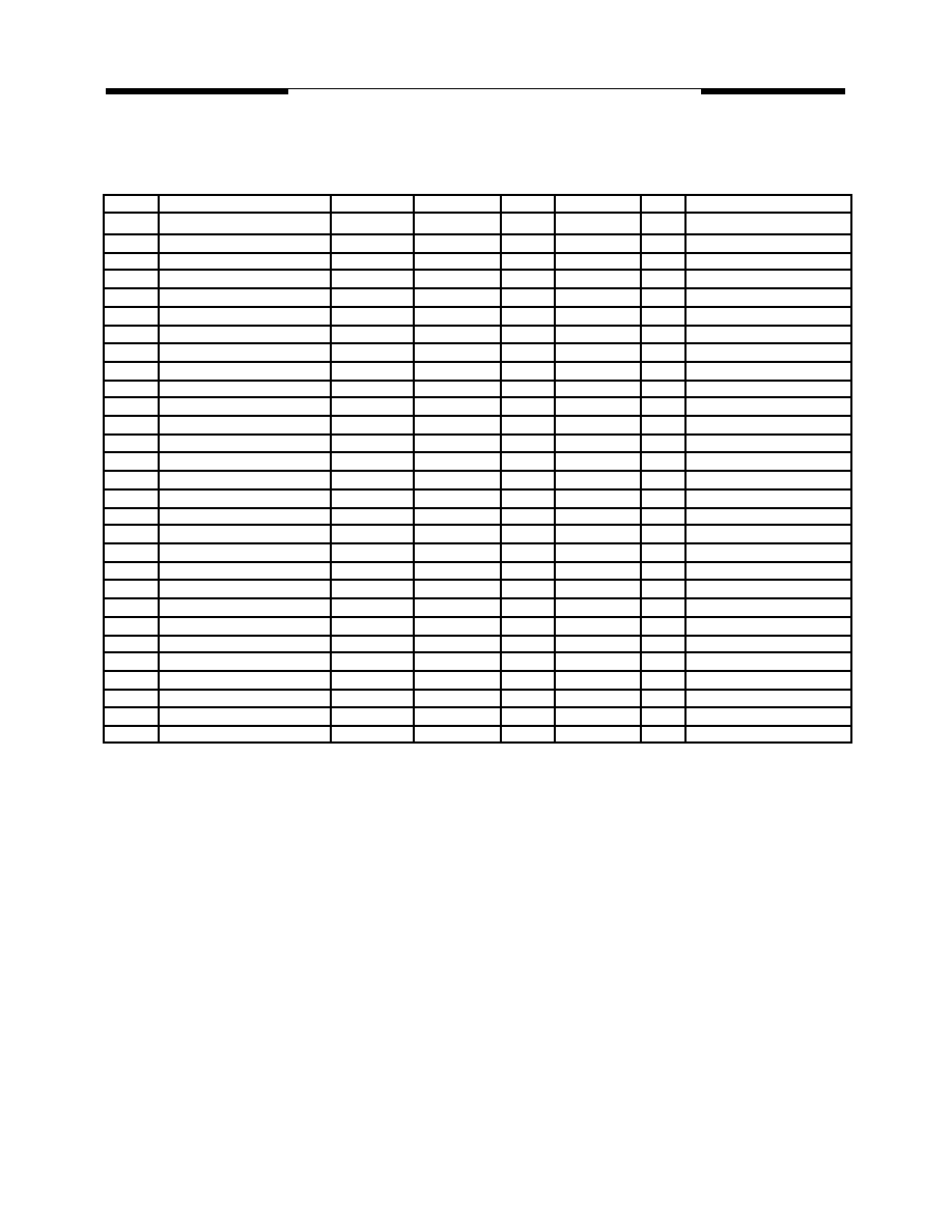
DC Characteristics
(16/25/40 MHz, typical operating conditons, valid for U20x2C series)
Symbol
V ILX
V ILE
V ILR
V IHX
V IHE
V IHR
V OLA
V OL0
V OL1
V OHA
V OH0
V OH1
V OH2
I OL0
I IL
I IH
I TL
I LI
R RES
R X
C IO
I CC
Parameter
Input Low Voltage
"
"
Input High Voltage
"
"
Output Low Voltage
"
"
Output High Voltage
"
"
"
"
"
"
"
Output Low Current
Logical 0 Input Current
Logical 1 Input Current
Logic Transition Current
Input Leakage Current
Reset Pulldown Resistance
Crystal feedback Resistance
Pin Capacitance
Power Supply Current
Valid
XTAL1
#EA
RES
XTAL1
#EA
RES
ALE, #PSEN
ports 0,3
ports 1,2
ALE, #PSEN
port 0
ports 1,3
port 2
ports 0,3
ports 1,2,3
port 0
ports 1,2,3
port 0
RES
XTAL1,2
Vdd
Vdd
Vdd
Min.
Typ.
Max
Unit
V
V
V
V
V
V
mV
mV
mV
V
V
V
V
V
V
V
V
mA
uA
uA
uA
uA
Kohm
Kohm
pF
mA
mA
uA
Test Conditions
I OL = 3.2 mA
I OL = 3.2 mA
I OL = 1.6 mA
I OH = -60 uA
I OH = -10 uA
I OH = -800 uA
I OH = -80 uA
I OH = -60 uA
I OH = -10 uA
I OH = -60 uA
I OH = -10 uA
V OL = 0.45V, note 1
V in = 0.45 V
V in = 5.0 V
V in = 2.0 V
0.45V < Vin < Vcc
Freq=1MHz, Ta=25
�J
Active mode, 16 MHz
Idle mode, 16MHz
Power down mode
-0.5
0
-0.5
70%Vcc
20%Vcc+0.9
70%Vcc
2.4
90%Vcc
2.4
90%Vcc
2.4
90%Vcc
2.4
90%Vcc
50
90
18
5
3
10
20%Vcc-0.1
20%Vcc-0.3
20%Vcc-0.1
Vcc+0.5
Vcc+0.5
Vcc+0.5
450
450
450
-50
1.5
-650
10
150
330
10
8
5
45
note 1 : no more than 80 mA I OLs for all 16-bit ports 0 & 3 output pins.
9
Rev. 1.0 February 1998
MOSEL VITELIC
MSU2052/U2032
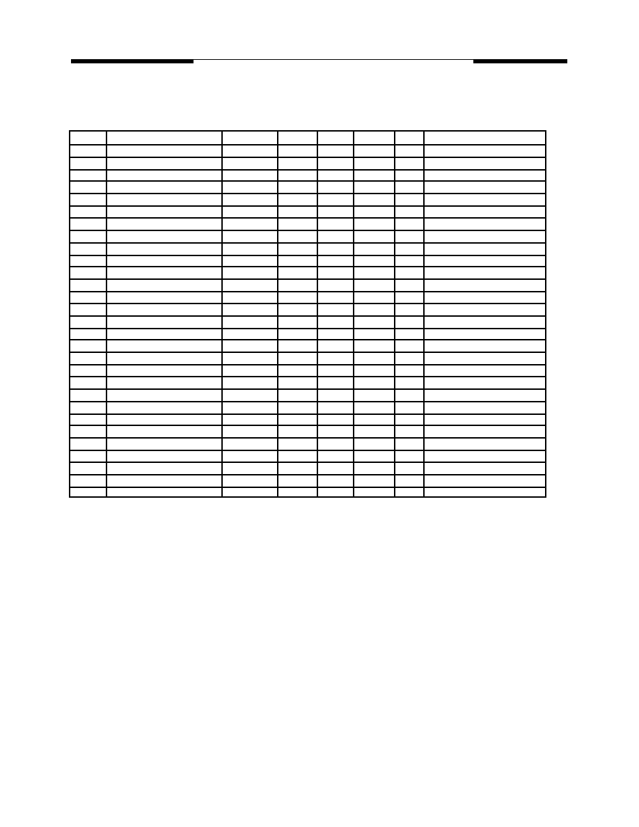
DC Characteristics
(16 MHz, typical operating conditons, valid for U20x2L series)
Symbol
V ILX
V ILE
V ILR
V IHX
V IHE
V IHR
V OLA
V OL0
V OL1
V OHA
V OH0
V OH1
V OH2
I IL
I IH
I TL
I LI
R RES
R X
C IO
I CC
Parameter
Input Low Voltage
"
"
Input High Voltage
"
"
Output Low Voltage
"
"
Output High Voltage
"
"
"
"
"
"
"
Logical 0 Input Current
Logical 1 Input Current
Logic Transition Current
Input Leakage Current
Reset Pulldown Resistance
Crystal feedback Resistance
Pin Capacitance
Power Supply Current
Valid
XTAL1
#EA
RES
XTAL1
#EA
RES
ALE, #PSEN
ports 0,3
ports 1,2
ALE, #PSEN
port 0
ports 1,3
port 2
ports 1,2,3
port 0
ports 1,2,3
port 0
RES
XTAL1,2
Vdd
Vdd
Vdd
Min.
Typ.
Max
Unit
mV
mV
mV
V
V
V
mV
mV
mV
V
V
V
V
V
V
V
V
uA
uA
uA
uA
Kohm
Kohm
pF
mA
mA
uA
Test Conditions
I OL = 3.2 mA
I OL = 3.2 mA
I OL = 1.6 mA
I OH = -60 uA
I OH = -10 uA
I OH = -800 uA
I OH = -80 uA
I OH = -60 uA
I OH = -10 uA
I OH = -60 uA
I OH = -10 uA
V in = 0.45 V
V in = 3.0 V
V in = 1.4 V
0.45V < Vin < Vcc
Freq=1MHz, Ta=25
�J
Active mode, 16 MHz
Idle mode, 16MHz
Power down mode
1.8
2.4
2.2
2.4
1.8
2.4
1.8
2.4
50
90
2
1
10
Vcc+0.3
Vcc+0.3
Vcc+0.3
400
400
400
45
1
250
8
150
330
10
7
4.5
45

10
Rev. 1.0 February 1998
MOSEL VITELIC
MSU2052/U2032
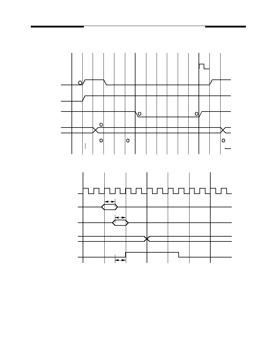
Data Memory Read Cycle Timing
Program Memory Read Cycle Timing
T12
T1
T2
T3
T4
T5
T6
T7
T8
T9
T10
T11
T12
T1
T2
OSC
ALE
#PSEN
#RD, #WR
PORT2
PORT0
ADDRESS A - A
15
8
ADDRESS A -A
15
8
1
2
5
7
3
3
4
6
8
Float
Float
A -A
Float
Float
Float
7
0
INST in
A -A
7
0
INST in
T12
T1
T2
T3
T4
T5
T6
T7
T8
T9
T10
T11
T12
T1
T2
OSC
ALE
#PSEN
#RD
PORT2
PORT0
ADDRESS A - A
15
8
1
2
5
7
3
3
4
6
8
Float
Float
A -A
Float
7
0
INST in
DATA in
T3
ADDRESS
or Flloat
11
Rev. 1.0 February 1998
MOSEL VITELIC
MSU2052/U2032
Data Memory Write Cycle Timing
T12
T1
T2
T3
T4
T5
T6
T7
T8
T9
T10
T11
T12
T1
T2
OSC
ALE
#PSEN
#WR
PORT2
PORT0
ADDRESS A - A
15
8
1
5
6
2
2
3
4
Float
A -A
7
0
DATA OUT
T3
ADDRESS
or Float
INST
X1
inputs P0, P1
inputs P2, P3
Output by
MOV Px,Src
RxD at Serial Port
Shift Clock
(Mode 0)
sampled
sampled
current data
next data
sampled
T7
T8
T9
T10
T11
T12
T1
T2
T3
T4
T5
T6
T7
T8
T6
I/O Ports Timing
12
Rev. 1.0 February 1998
MOSEL VITELIC
MSU2052/U2032
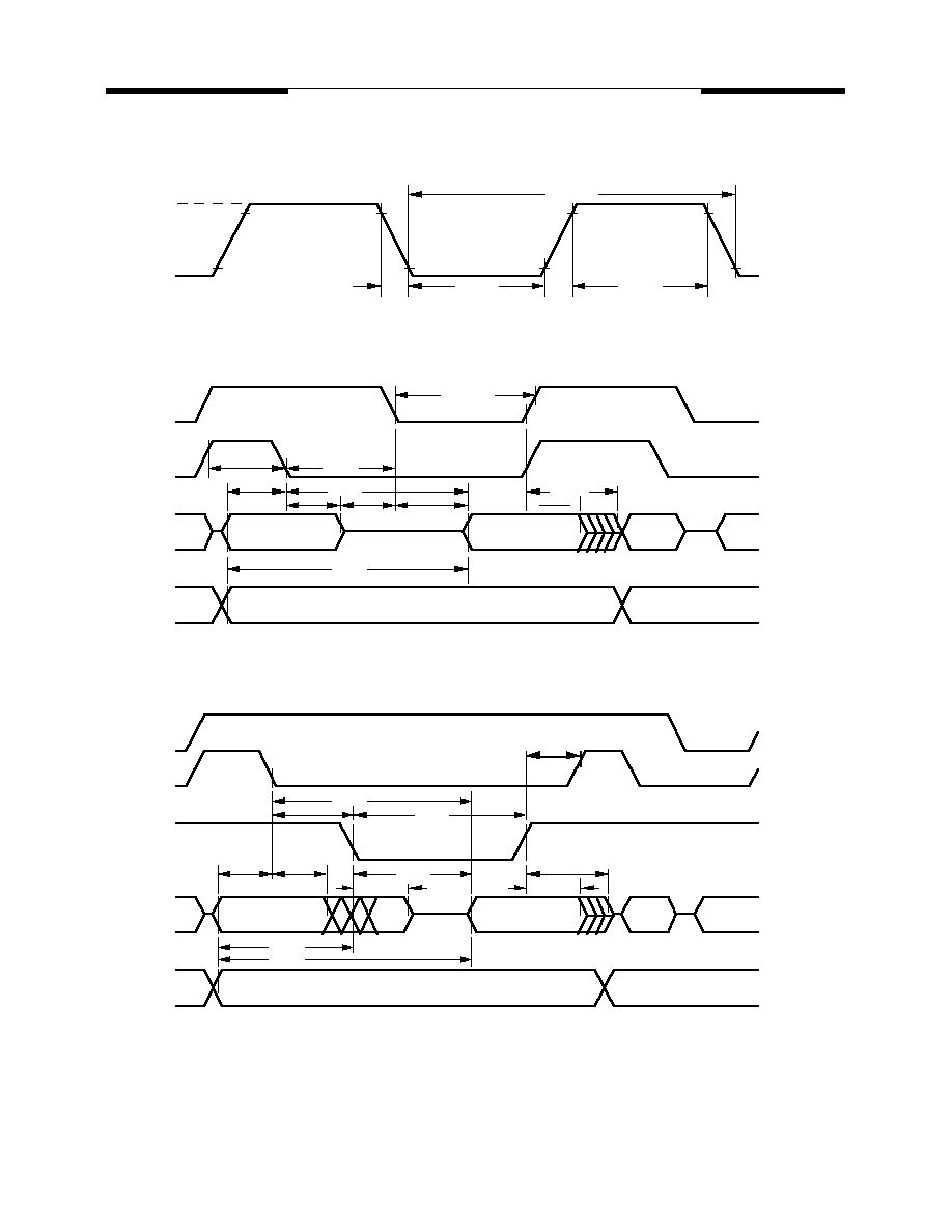
T AVDV
T AVLL
T LLAX
T AVYL
T RLAZ
T RLDV
T RHDX
T RHDZ
T YHLH
T LLYL
T RLRH
T LLDV
P2.0-P2.7 or A8-A15 from DPH
A0-A7
from Ri or
DATA IN
A0-A7
From
INSTR.
IN
A8-A15 from PCH
PORT 2
PORT 0
#RD
ALE
#PSEN
Tm.I External Program Memory Read Cycle
Tm.II External Data Memory Read Cycle
#PSEN
ALE
PORT 0
PORT 2
A8 - A15
A8 - A15
A0 - A7
Instruction. IN
A0 - A7
T AVIV
T LLIV
T AVLL
T LLAX
T PLAZ
T PLIV
T LLPL
T LHLL
T PXIZ
T PXIX
T PLPH
Timing Critical, Requirement of External Clock
(Vss=0.0V is assumed)
T CLCL
T CHCL
T CLCX
T CLCH
T CHCX
Vdd-0.5V
0.45V
70%Vdd
20%Vdd-0.1V
13
Rev. 1.0 February 1998
MOSEL VITELIC
MSU2052/U2032
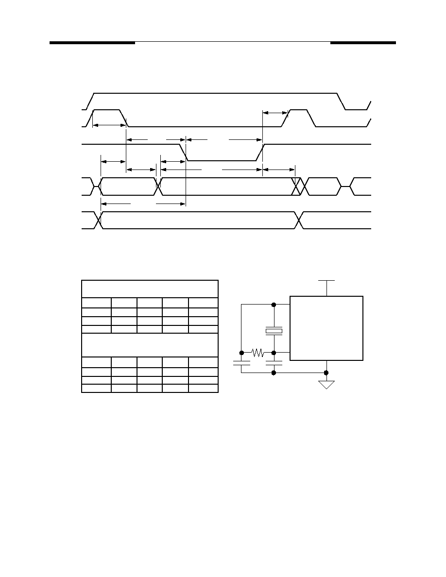
T AVLL
T LLAX
T AVYL
T YHLH
T LLYL
T WLWH
P2.0-P2.7 or A8-A15 from DPH
A0-A7
from Ri or
DPL
DATA OUT
A0-A7
From
PCL
INSTR.
IN
A8-A15 from PCH
PORT 2
PORT 0
#WR
ALE
#PSEN
Tm.III External Data Memory Write Cycle
T QVWX
T WHQX
T LHLL
X'tal
C1
C2
R
3 MHz
15 pF
15 pF
open
12 MHz
30 pF
30 pF
open
16 MHz
30 pF
30 pF
open
X1
X2
MSU2052
MSU2032
X'tal
R
Application Reference
C1
C2
T QVWH
6 MHz
15 pF
15 pF
open
X'tal
C1
C2
R
12 MHz
30 pF
30 pF
open
25 MHz
15 pF
15 pF
62 Kohm
40 MHz
5 pF
5 pF
4.7 Kohm
16 MHz
30 pF
30 pF
open
Valid for U2052L16/ U2032L16
Valid for U2052C16/ U2032C16/
U2052C25/ U2032C25/
U2052C40/ U2032C40

14
Rev. 1.0 February 1998
MOSEL VITELIC
MSU2052/U2032
Note:
1.Dimension D Max & S include mold flash or tie bar
burrs.
2.Dimension E1 does not include interlead flash.
3.Dimenseion D & E1 include mold mismatch and are
determined at the mold parting line.
4.Dimension B1 does not include dambar protrusion/
infrusion.
5.Controlling dimension is inch.
6.General appearance spec. should base on final
visual
inspection spec.
40L 600mil PDIP Information
�\
C
eA
E
E1
D
A1
S
e1
B1
B
A2
A
L
Symbol
A
A1
A2
B
B1
C
D
E
E1
e1
L
�\
eA
S
Dimension in Inch
minimal/maximal
- / 0.210
0.010 / -
0.150 / 0.160
0.016 / 0.022
0.048 / 0.054
0.008 / 0.014
- / 2.070
0.590 / 0.610
0.540 / 0.552
0.090 / 0.110
0.120 / 0.140
0.630 / 0.670
Dimension in mm
minimal/maximal
- / 5.33
0.25 / -
3.81 / 4.06
0.41 / 0.56
1.22 / 1.37
0.20 / 0.36
- / 52.58
14.99 / 15.49
13.72 / 14.02
2.29 / 2.79
3.05 / 3.56
16.00 / 17.02
- / 2.29
0
�
/ 15
�
0
�
/ 15
�
/ 0.090

15
Rev. 1.0 February 1998
MOSEL VITELIC
MSU2052/U2032
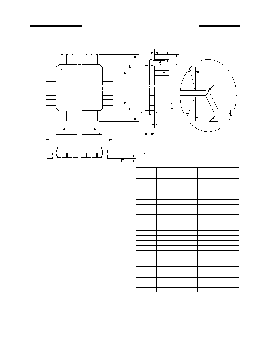
Note:
1.Dimension D & E does not include interlead flash.
2.Dimension b1 does not include dambar protrusion/
intrusion.
3.Controlling dimension:Inch
4.General appreance spec. should base on final visual
inspection spec.
44L Plastic Leaded Chip Carrier (PLCC)
6
7
D
H
D
E H
E
0
e
G
D
b1
b
C
G
E
L
A2
A
A1
y
Symbol
A
A1
A2
b1
b
C
D
E
e
GD
GE
HD
HE
L
Dimension in Inch
minimal/maximal
- / 0.185
0.020 / -
0.145 / 0.155
0.026 / 0.032
0.016 / 0.022
0.008 / 0.014
0.648 / 0.658
0.648 / 0.658
0.050 BSC
0.590 / 0.630
0.590 / 0.630
0.680 / 0.700
0.680 / 0.700
0.090 / 0.110
- / 0.004
/
Dimension in mm
minimal/maximal
- / 4.70
0.51 / -
3.68 / 3.94
0.66 / 0.81
0.41 / 0.56
0.20 / 0.36
16.46 / 16.71
16.46 / 16.71
1.27BSC
14.99 / 16.00
14.99 / 16.00
17.27 / 17.78
17.27 / 17.78
2.29 / 2.79
- / 0.10
y
/
16
Rev. 1.0 February 1998
MOSEL VITELIC
MSU2052/U2032
Note:
Dimension D1 and E1 do not include mold
protrustion. Allowance protrusion is 0.25mm per side.
Dimensions D1 and E1 do include mold mismatch
and are determined at datum plane.
Dimension b does not include dambar protrusion.
Allowance dambar protrusion shall be 0.08 mm total
in excess of the b dimension at maximum material
condition. Dambar cannot be located on the lower
radius or the lead foot.
E2
E1
E
D2 D1 D
seating plane
C
A2
A1
A
C
L
L1
S
e
b
b
R2
R1
3
2
44L Plastic Quad Flat Package
1.
2.
01
Gage Plane
0.25 mm
Symbol
A
A1
A2
b
c
D
D1
D2
E
E1
E2
e
L
L1
R1
R2
S
Dimension in Inch
minimal/maximal
- / 0.100
0.006 / 0.014
0.071 / 0.087
0.012 / 0.018
0.004 / 0.009
0.520 BSC
0.394 BSC
0.315
0.520 BSC
0.394 BSC
0.315
0.031 BSC
0.029 / 0.041
0.063
0.005 / -
0.005 / 0.012
Dimension in mm
minimal/maximal
- / 2.55
0.15 / 0.35
1.80 / 2.20
0.30 / 0.45
0.09 / 0.20
13.20 BSC
10.00 BSC
8.00
13.20 BSC
10.00 BSC
8.00
0.80 BSC
0.73 / 1.03
1.60
0.13 / -
0.13 / 0.30
0.20 / -
as left
as left
as left
as left
C
1
2
3
0
�
/ 7
�
0
�
/ -
10
�
REF
7
�
REF
0.004
0.10
0.008 / -

17
Rev. 1.0 February 1998
MOSEL VITELIC
MSU2052/U2032
Note:
Dimension D1 and E1 do not include mold
protrustion. Allowance protrusion is 0.25mm per side.
D1 and E1 are maximal plastic body size dimensions
including mold mismatch.
Dimension b does not include dambar protrusion.
Allowance dambar protrusion shall not cause the
lead width to exceed the maximal b dimension by
more than 0.08 mm.
Dambar can not be located on the lower radius or the
foot. Minimal space between protrusion and an
adjacent lead is 0.07 mm for 0.4 mm and 0.5 mm
pitch packages.
44L Low profile Quad Flat Package
1.
2.
3.
E2
E1
E
D2 D1 D
seating plane
C
A2
A1
A
C
L
L1
S
e
b
b
R2
R1
3
2
01
Gage Plane
0.25 mm
Symbol
A
A1
A2
b
c
D
D1
D2
E
E1
E2
e
L
L1
R1
R2
S
Dimension in Inch
minimal/maximal
- / 0.063
0.002 / 0.006
0.053 / 0.057
0.012 / 0.018
0.004 / 0.008
0.472 BSC
0.393 BSC
0.315
0.472 BSC
0.393 BSC
0.315
0.031 BSC
0.018 / 0.030
0.039 REF
0.003 / -
0.003 / 0.008
Dimension in mm
minimal/maximal
- / 1.60
0.05 / 0.15
1.35 / 1.45
0.30 / 0.45
0.09 / 0.20
12.00 BSC
10.00 BSC
8.00
12.00 BSC
10.00 BSC
8.00
0.80 BSC
0.45 / 0.75
1.00 REF
0.08 / -
0.08 / 0.20
0.20 / -
as left
as left
as left
as left
C
1
2
3
0
�
/ 7
�
0
�
/ -
11
�
/13
�
11
�
/13
�
0.004
0.10
0.008 / -
18
Rev. 1.0 February 1998
MOSEL VITELIC
MSU2052/U2032
Bonding Information
pid 252* 12/96
pid 252** 01/97
pid 252*** 02/97
pid 252A 02/98
Index
PAD-NAME
P1.5
P1.6
P1.7
RES
P3.0
P3.1
P3.2
P3.3
P3.4
P3.5
P3.6
P3.7
XTAL2
XTAL1
VSS
VSS
VSS
P2.0
P2.1
P2.2
P2.3
P2.4
1
2
3
4
5
6
7
8
9
10
11
12
13
14
15
16
17
18
19
20
21
22
Index
PAD-NAME
P2.5
P2.6
P2.7
#PSEN
ALE
#EA
P0.7
P0.6
P0.5
P0.4
P0.3
P0.2
P0.1
P0.0
VDD
VDD
P1.0
P1.1
P1.2
P1.3
P1.4
23
24
25
26
27
28
29
30
31
32
33
34
35
36
37
38
39
40
41
42
43
X-COORD
Y-COORD
237
400
559
722
882
1044
1204
1366
1526
1688
1931
1931
1931
1931
1931
1931
1931
1931
1931
1931
1931
1931
X-COORD
1688
1526
1366
1204
1044
882
722
559
400
237
168
168
168
168
168
168
168
168
168
168
168
186
186
186
186
186
186
186
186
186
186
310
537
769
1090
1291
1442
1593
1791
2016
2243
2468
2696
Y-COORD
2874
2874
2874
2874
2874
2874
2874
2874
2874
2874
2595
2367
2142
1915
1717
1566
1369
1144
917
692
464
1
2
3
4
5
6
7
8
9
10
32
31
30
29
28
27
26
25
24
23
11 12 13 14 15 16 17 18 19 20 21 22
43 42 41 40 39 38 37 36 35 34 33
MSU2052/U2032
2200 x 3160 (
�
m)
PAD SIZE : 90 x 90 (
�
m)
substrate should be bonded to Vss
Logo
19
Rev. 1.0 February 1998
MOSEL VITELIC
MSU2052/U2032
To: Mosel Vitelic Inc.
886-3-578-4732 (fax #)
Attn: Sales & Marketing Department
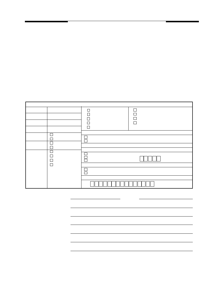
Product Request Form
We hereby request MVI to start producing MSU2052 which is specified below.
Please send us the product code and a hardcopy of data code as well as data code file duplicated on floppy
diskette. No further confirmation is necessary.
Production will start automatically once you receive our data code and verify that the checksum is match.
Mass Production of the captioned device shall be done in accordance with the purchase order(s) issued by
us or a company specified by us. All terms and conditions are based on the development agreement and/or
contract signed between MVI and us.
Data Code Descriptions
Code Length
File Length
File Name
Checksum
Unused
Data Byte
Format
Media
h
00h filled
FFh filled
HEX format
Binary code format
EPROM
8751 chip
File on Floppy
E-mail file
Top Marking (fill only for packaged)
IC descriptions
Dice form
P type = 40L-PDIP
J type = 44L-PLCC
Q type = 44L-PQFP
L type = 44L-LQFP
Phone # :
Company Name :
Signature :
Name (Typed) :
Position Title :
Department, Section :
Signature Date :
Fax # :
Date code location descriptions
Use MVI logo, date code and part number
Use my specifications as described below
Use regular date code as MVI's
Leave it as blank
use right side five letters
Leave it blank
Use my specifications as attachment
Logo Specifications
Part number specified, less than 15 digits
Specify below fields only for customer top marking
U2052L16, 16 MHz low working voltage
U2052C16, 16 MHz
U2052C25, 25 MHz
U2052C40, 40 MHz

20
Rev. 1.0 February 1998
MOSEL VITELIC
MSU2052/U2032
To: Mosel Vitelic Inc.
886-3-578-4732 (fax#)
Attn: Sales & Marketing Department
Logo Top Marking Request & spec.
We hereby request MVI to have our logo printed on top of the device package. Below is the
specification of our logo in 20:1 scale base. This logo diagram is clear enough and is able to be
shrunk directly to fit into available top marking area described on page.
Phone # :
Company Name :
Signature :
Name (Typed) :
Position Title :
Department, Section :
Signature Date :
Fax # :

MOSEL VITELIC
WORLDWIDE OFFICES
MSU2052/U2032
� Copyright 1998, MOSEL VITELIC Inc.
1/98
Printed in U.S.A.
MOSEL VITELIC
3910 N. First Street, San Jose, CA 95134-1501 Ph: (408) 433-6000 Fax: (408) 433-0952 Tlx: 371-9461
U.S. SALES OFFICES
The information in this document is subject to change without
notice.
MOSEL VITELIC makes no commitment to update or keep cur-
rent the information contained in this document. No part of this
document may be copied or reproduced in any form or by any
means without the prior written consent of MOSEL-VITELIC.
MOSEL VITELIC subjects its products to normal quality control
sampling techniques which are intended to provide an assurance
of high quality products suitable for usual commercial applica-
tions. MOSEL VITELIC does not do testing appropriate to provide
100% product quality assurance and does not assume any liabil-
ity for consequential or incidental arising from any use of its prod-
ucts. If such products are to be used in applications in which
personal injury might occur from failure, purchaser must do its
own quality assurance testing appropriate to such applications.
U.S.A.
3910 NORTH FIRST STREET
SAN JOSE, CA 95134
PHONE: 408-433-6000
FAX: 408-433-0185
HONG KONG
19 DAI FU STREET
TAIPO INDUSTRIAL ESTATE
TAIPO, NT, HONG KONG
PHONE: 852-2665-4883
FAX: 852-2664-7535
TAIWAN
7F, NO. 102
MIN-CHUAN E. ROAD, SEC. 3
TAIPEI
PHONE: 886-2-2545-1213
FAX: 886-2-2545-1209
1 CREATION ROAD I
SCIENCE BASED IND. PARK
HSIN CHU, TAIWAN, R.O.C.
PHONE: 886-3-578-3344
FAX: 886-3-579-2838
JAPAN
WBG MARINE WEST 25F
6, NAKASE 2-CHOME
MIHAMA-KU, CHIBA-SHI
CHIBA 261-71
PHONE: 81-43-299-6000
FAX: 81-43-299-6555
IRELAND & UK
BLOCK A UNIT 2
BROOMFIELD BUSINESS PARK
MALAHIDE
CO. DUBLIN, IRELAND
PHONE: +353 1 8038020
FAX: +353 1 8038049
GERMANY
(CONTINENTAL
EUROPE & ISRAEL )
71083 HERRENBERG
BENZSTR. 32
GERMANY
PHONE: +49 7032 2796-0
FAX: +49 7032 2796 22
NORTHWESTERN
3910 NORTH FIRST STREET
SAN JOSE, CA 95134
PHONE: 408-433-6000
FAX: 408-433-0185
NORTHEASTERN
SUITE 436
20 TRAFALGAR SQUARE
NASHUA, NH 03063
PHONE: 603-889-4393
FAX: 603-889-9347
SOUTHWESTERN
SUITE 200
5150 E. PACIFIC COAST HWY.
LONG BEACH, CA 90804
PHONE: 562-498-3314
FAX: 562-597-2174
CENTRAL & SOUTHEASTERN
604 FIELDWOOD CIRCLE
RICHARDSON, TX 75081
PHONE: 972-690-1402
FAX: 972-690-0341