 | –≠–ª–µ–∫—Ç—Ä–æ–Ω–Ω—ã–π –∫–æ–º–ø–æ–Ω–µ–Ω—Ç: V62C31864 | –°–∫–∞—á–∞—Ç—å:  PDF PDF  ZIP ZIP |

MOSEL VITELIC
1
V62C31864
2.7 VOLT 8K X 8 STATIC RAM
PRELIMINARY
V62C31864 Rev. 1.6 August 1998
Features
s
High-speed: 35, 70 ns
s
Ultra low DC operating current of 2mA (Max.)
s
Low Power Dissipation:
≠ TTL Standby: 1 mA (Max.)
≠ CMOS Standby: 10
m
A (Max.)
s
Fully static operation
s
All inputs and outputs directly compatible
s
Three state outputs
s
Ultra low data retention current (V
CC
= 2V)
s
Extended operating voltage: 2.7V≠3.6V
s
Packages
≠ 28-pin TSOP (Standard)
≠ 28-pin 300 mil SOP (450 mil pin-to-pin)
Description
The V62C31864 is a 65,536-bit static random
access memory organized as 8,192 words by 8
bits. It is built with MOSEL VITELIC's high
performance CMOS process. Inputs and three-
state outputs are TTL compatible and allow for
direct interfacing with common system bus
structures.
Device Usage Chart
Operating
Temperature
Range
Package Outline
Access Time (ns)
Power
Temperature
Mark
T
F
35
70
L
LL
0
∞
C to 70
∞
C
∑
∑
∑
∑
∑
∑
Blank
≠40
∞
C to +85
∞
C
∑
∑
∑
∑
I
Functional Block Diagram
Row
Decoder
512 x 128
Memory Array
Input
Data
Circuit
Column I/O
Column Decoder
Control
Circuit
V
CC
GND
A
0
31864 01
A
8
I/O
0
I/O
7
CE
2
OE
WE
CE
1
A
9
A
12

2
V62C31864 Rev. 1.6 August 1998
MOSEL VITELIC
V62C31864
Pin Descriptions
A
0
≠A
12
Address Inputs
These 13 address inputs select one of the 8,192 x 8
bit segments in the RAM.
CE
1
, CE
2
Chip Enable Inputs
CE
1
is active LOW and CE
2
is active HIGH. Both
chip enables must be active to read from or write to
the device. If either chip enable is not active, the
device is deselected and is in a standby power
mode. The I/O pins will be in the high-impedance
state when deselected.
OE
Output Enable Input
The Output Enable input is active LOW. When OE
is LOW with CE
1
LOW, CE
2
HIGH, and WE HIGH,
data of the selected memory location will be
available on the I/O pins. When OE is HIGH, the I/O
pins will be in the high impedance state.
WE
Write Enable Input
An active LOW input, WE input controls read and
write operations. When CE
1
and WE inputs are
both LOW with CE
2
HIGH, the data present on the
I/O pins will be written into the selected memory
location.
I/O
0
≠I/O
7
Data Input and Data Output Ports
These 8 bidirectional ports are used to read data
from and write data into the RAM.
V
CC
Power Supply
GND
Ground
Pin Configurations (Top View)
28-Pin SOP
28-Pin TSOP (Standard)
V
CC
A
8
A
9
A
11
A
10
OE
I/O
0
I/O
1
I/O
2
GND
A
0
A
1
A
2
A
3
A
4
A
5
I/O
7
I/O
6
I/O
5
I/O
4
51864 02
CE
2
WE
1
2
3
4
5
6
7
8
9
10
11
12
13
14
28
27
26
25
24
23
22
21
20
19
18
17
16
15
NC
A
12
A
6
A
7
I/O
3
CE
1
OE
A11
A9
A8
CE2
WE
VCC
NC
A12
A7
A6
A5
A4
A3
A10
CE1
I/O7
I/O6
I/O5
I/O4
I/O3
GND
I/O2
I/O1
I/O0
A0
A1
A2
22
23
24
25
26
27
28
1
2
3
4
5
6
7
21
20
19
18
17
16
15
14
13
12
11
10
9
8
51864 03

MOSEL VITELIC
V62C31864
3
V62C31864 Rev. 1.6 August 1998
Part Number Information
Absolute Maximum Ratings
(1)
NOTE:
1.
Stresses greater than those listed under "Absolute Maximum Ratings" may cause permanent damage to the device. This is a stress
rating only and functional operation of the device at these or any other conditions above those indicated in the operational sections
of this specification is not implied. Exposure to absolute maximum rating conditions for extended periods may affect
reliability.
Symbol
Parameter
Commercial
Industrial
Units
V
CC
Supply Voltage
-0.5 to V
CC
+0.5
-0.5 to V
CC
+0.5
V
V
N
Input Voltage
-0.5 to V
CC
+0.5
-0.5 to V
CC
+0.5
V
V
DQ
Input/Output Voltage Applied
V
CC
+ 0.3
V
CC
+ 0.3
V
T
BIAS
Temperature Under Bias
-10 to +125
-65 to +135
∞
C
T
STG
Storage Temperature
-55 to +125
-65 to +150
∞
C
SRAM
FAMILY
C = CMOS PROCESS
62 = ASYNCHRONOUS, SLOW
31 = 2.7V ≠ 3.6V
OPERATING
VOLTAGE
64K
ORGANIZATION
PKG
SPEED
31864 05
PWR.
62
C
8
31
64
≠
MOSEL-VITELIC
MANUFACTURED
V
8 = 8-bit
35 ns
70 ns
TEMP.
BLANK = 0
°
C to 70
°
C
I = -40
°
C to +85
°
C
L = LOW POWER
LL =DOUBLE LOW POWER
F = 330 mil SOP
T = TSOP standard
DENSITY
Capacitance*
T
A
= 25
∞
C, f = 1.0MHz
NOTE:
* This parameter is guaranteed and not tested.
Truth Table
NOTE:
X = Don't Care, L = LOW, H = HIGH
Symbol
Parameter Conditions
Max.
Unit
C
IN
Input Capacitance
V
IN
= 0V
6
pF
C
OUT
Output Capacitance
V
I/O
= 0V
8
pF
Mode
CE
1
CE
2
OE
WE
I/O
Operation
Standby
H
X
X
X
High Z
Standby
X
L
X
X
High Z
Output Disable
L
H
H
H
High Z
Read
L
H
L
H
D
OUT
Write
L
H
X
L
D
IN

4
V62C31864 Rev. 1.6 August 1998
MOSEL VITELIC
V62C31864
DC Electrical Characteristics
(over all temperature ranges, V
CC
= 2.7V ≠ 3.6V)
NOTES:
1.
These are absolute values with respect to device ground and all overshoots due to system or tester noise are included.
2.
V
IL
(Min.) = -3.0V for pulse width < 20ns.
3.
f
MAX
= 1/t
RC
.
4.
Maximum values.
Symbol
Parameter
Test Conditions
Min.
Typ.
Max.
Units
V
CC
Power Supply Voltage
2.7
--
3.6
V
V
IL
Input LOW Voltage
(1,2)
-0.3
--
0.4
V
V
IH
Input HIGH Voltage
(1)
2.2
--
V
CC
+0.3
V
I
IL
Input Leakage Current
V
CC
= Max, V
IN
= 0V to V
CC
-2
--
2
m
A
I
OL
Output Leakage Current
V
CC
= Max, CE = V
IH
, V
OUT
= 0V to V
CC
-2
--
2
m
A
V
OL
Output LOW Voltage
V
CC
= Min, I
OL
= 2.1mA
--
--
0.4
V
V
OH
Output HIGH Voltage
V
CC
= Min, I
OH
= -1mA
2.4
--
--
V
Symbol
Parameter
Com.
(4)
Ind.
(4)
Units
I
CC
Operating Power Supply Current, CE
1
= V
IL
, CE
2
= V
IH
,
Output Open, V
CC
= Max., f = 0
2
2
mA
I
CC1
Average Operating Current, CE
1
= V
IL
, CE
2
= V
IH
,
Output Open, V
CC
= Max., f = f
MAX
(3)
40
40
mA
I
SB
TTL Standby Current
CE
1
≥
V
IH
, CE
2
£
V
IL
, V
CC
= Max.
L
2
3
mA
LL
1
1
I
SB1
CMOS Standby Current, CE
1
≥
V
CC
≠ 0.2V, CE
2
£
0.2V,
V
IN
≥
V
CC
≠ 0.2V or V
IN
£
0.2V, V
CC
= Max.
L
40
50
m
A
LL
10
15
AC Test Conditions
AC Test Loads and Waveforms
Key to Switching Waveforms
Input Pulse Levels
0 to 3V
Input Rise and Fall Times
5 ns
Timing Reference Levels
1.5V
Output Load
see below
+3V
1103
Ω
1554
Ω
* Includes scope and jig capacitance
I/O Pins
C
L
= 30 pF*
51864 06
WAVEFORM
INPUTS
OUTPUTS
MUST BE
STEADY
WILL BE
STEADY
MAY CHANGE
FROM H TO L
WILL BE
CHANGING
FROM H TO L
MAY CHANGE
FROM L TO H
WILL BE
CHANGING
FROM L TO H
DON'T CARE:
ANY CHANGE
PERMITTED
CHANGING:
STATE
UNKNOWN
DOES NOT
APPLY
CENTER
LINE IS HIGH
IMPEDANCE
"OFF" STATE
MOSEL VITELIC
V62C31864
5
V62C31864 Rev. 1.6 August 1998
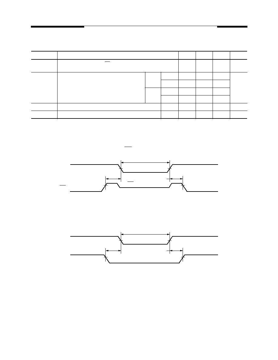
Data Retention Characteristics
NOTES:
1.
t
RC
= Read Cycle Time
2.
T
A
= +25
∞
C.
Low V
CC
Data Retention Waveform (1) (CE
1
Controlled)
Low V
CC
Data Retention Waveform (2) (CE
2
Controlled)
Symbol
Parameter
Min.
Typ.
(2)
Max.
Units
V
DR
V
CC
for Data Retention
CE
1
≥
V
CC
≠ 0.2V, CE
2
£
0.2V,
V
IN
≥
V
CC
≠ 0.2V, or V
IN
£
0.2V
2.0
--
3.6
V
I
CCDR
Data Retention Current
CE
1
≥
V
DR
≠ 0.2V, CE
2
£
0.2V,
V
IN
≥
V
CC
≠ 0.2V, or V
IN
£
0.2V
Com'l
L
--
0.5
40
m
A
LL
--
0.5
10
Ind.
L
--
--
45
LL
--
--
15
t
CDR
Chip Deselect to Data Retention Time
0
--
--
ns
t
R
Operation Recovery Time (see Retention Waveform)
t
RC
(1)
--
--
ns
V
CC
31864 14
Data Retention Mode
CE
1
≥
V
CC
≠ 0.2V
CE
1
2.2V
2.2V
2.7V
t
CDR
t
R
V
DR
≥
2V
2.7V
V
CC
31864 15
Data Retention Mode
CE
2
≤
0.2V
CE
2
2.2V
2.2V
2.7V
t
CDR
t
R
V
DR
≥
2V
2.7V
6
V62C31864 Rev. 1.6 August 1998
MOSEL VITELIC
V62C31864
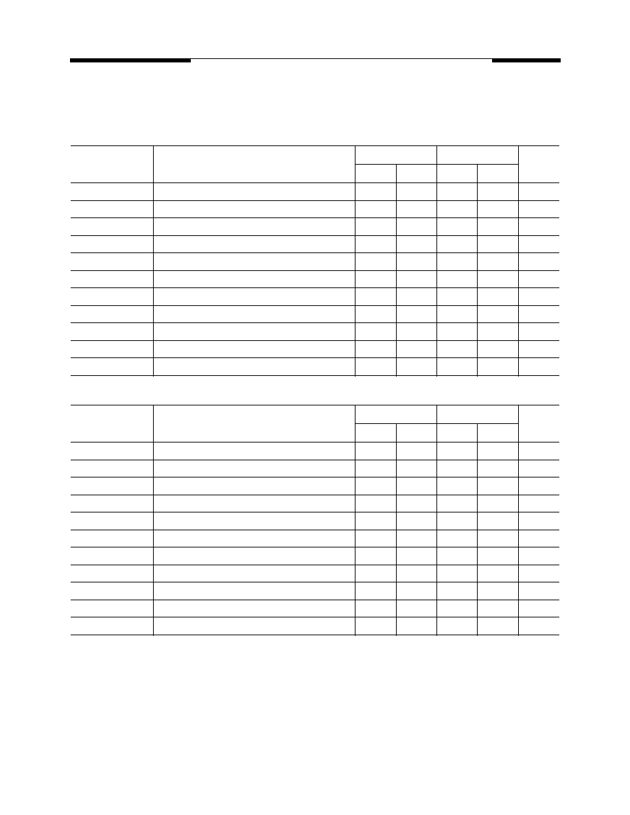
AC Electrical Characteristics
(over all temperature ranges, V
CC
= 2.7V ≠ 3.6V)
Read Cycle
Write Cycle
Parameter
Name
Parameter
-35
-70
Unit
Min.
Max.
Min.
Max.
t
RC
Read Cycle Time
35
--
70
--
ns
t
AA
Address Access Time
--
35
--
70
ns
t
ACS1
Chip Enable Access Time
--
35
--
70
ns
t
ACS2
Chip Enable Access Time
--
35
--
70
ns
t
OE
Output Enable to Output Valid
--
15
--
30
ns
t
CLZ1
Chip Enable to Output in Low Z
5
--
5
--
ns
t
CLZ2
Chip Enable to Output in Low Z
5
--
5
--
ns
t
OLZ
Output Enable to Output in Low Z
5
--
5
--
ns
t
CHZ
Chip Disable to Output in High Z
0
20
0
20
ns
t
OHZ
Output Disable to Output in High Z
0
20
0
20
ns
t
OH
Output Hold from Address Change
5
--
5
--
ns
Parameter
Name
Parameter
-35
-70
Unit
Min.
Max.
Min.
Max.
t
WC
Write Cycle Time
35
--
70
--
ns
t
CW1
Chip Enable to End of Write
35
--
70
--
ns
t
CW2
Chip Enable to End of Write
35
--
70
--
ns
t
AS
Address Setup Time
0
--
0
--
ns
t
AW
Address Valid to End of Write
35
--
70
--
ns
t
WP
Write Pulse Width
25
--
50
--
ns
t
WR
Write Recovery Time
0
--
0
--
ns
t
WHZ
Write to Output High-Z
0
20
0
25
ns
t
DW
Data Setup to End of Write
25
--
30
--
ns
t
DH
Data Hold from End of Write
0
--
0
--
ns
t
OW
Output Active from End of Write
5
--
5
--
ns
MOSEL VITELIC
V62C31864
7
V62C31864 Rev. 1.6 August 1998
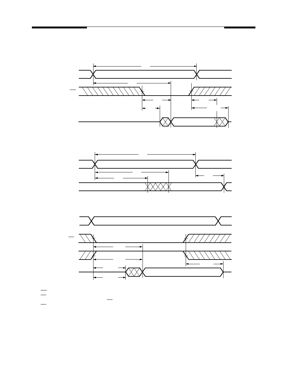
Switching Waveforms (Read Cycle)
Read Cycle 1
(1, 2)
Read Cycle 2
(1, 2, 4)
Read Cycle 3
(1, 3, 4)
NOTES:
1.
WE = V
IH
.
2.
CE
1
= V
IL
and CE
2
= V
IH
.
3.
Address valid prior to or coincident with CE
1
transition LOW and/or CE
2
transition HIGH.
4.
OE = V
IL
.
5.
Transition is measured
±
500mV from steady state with C
L
= 5pF. This parameter is guaranteed and not 100% tested.
ADDRESS
51864 11
OE
I/O
t
RC
t
AA
t
OE
t
OLZ
t
OH
t
OHZ
(5)
ADDRESS
I/O
51864 09
t
RC
t
AA
t
OH
t
OH
51864 10
I/O
ADDRESS
CE
1
CE
2
t
ACS1
t
ACS2
t
CLZ1
(5)
t
CLZ2
(5)
t
CHZ
(5)

8
V62C31864 Rev. 1.6 August 1998
MOSEL VITELIC
V62C31864
Switching Waveforms (Write Cycle)
Write Cycle 1 (WE Controlled)
(4)
Write Cycle 2 (CE Controlled)
(4)
NOTES:
1.
The internal write time of the memory is defined by the overlap of CE
1
and CE
2
active and WE low. Both signals must be active to
initiate and any one signal can terminate a write by going inactive. The data input setup and hold timing should be referenced to
the second transition edge of the signal that terminates the write.
2.
t
WR
is measured from the earlier of CE
1
or WE going HIGH, or CE
2
going LOW at the end of the write cycle.
3.
During this period, I/O pins are in the output state so that the input signals of opposite phase to the outputs must not be applied.
4.
OE = V
IL
or V
IH
. However it is recommended to keep OE at V
IH
during write cycle to avoid bus contention.
5.
If CE
1
is LOW and CE
2
is HIGH during this period, I/O pins are in the output state. Then the data input signals of opposite phase
to the outputs must not be applied to them.
6. t
CW
is measured from CE
1
going LOW or CE
2
going HIGH to the end of write.
ADDRESS
OUTPUT
INPUT
CE
1
CE
2
WE
51864 12
t
WC
t
CW
(6)
t
CW
(6)
t
DW
t
DH
t
AW
t
WR
(2)
t
WHZ
t
WP
(1)
t
AS
ADDRESS
OUTPUT
High-Z
INPUT
CE
1
CE
2
WE
51864 13
t
WC
t
DW
t
DH
t
AW
t
CW
(6)
t
CW
(6)
t
WR
(2)
t
AS
(4)
(5)
MOSEL VITELIC
V62C31864
9
V62C31864 Rev. 1.6 August 1998
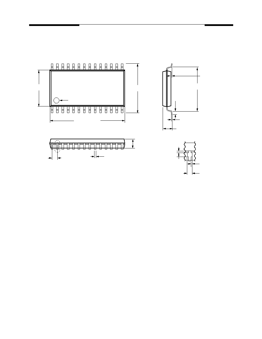
Package Diagrams
28-pin 330 mil SOP
0.465
±
0.012
[11.81
±
0.305]
0.008 [0.203]
0.402
±
0.012
[10.21
±
0.203]
0.713 [18.11] TYP
0.050 [1.27] TYP
0.018
±
0.004
[0.457
±
0.102]
0.006
±
0.002
[0.152
±
0.051]
INDEX
0.339
±
0.008
[8.61
±
0.203]
"A"
0 MIN
(STAND OFF)
0.031
±
0.008
[0.787
±
0.203]
0.112 [0.285] MAX
0.024 [0.610]
0.008 [0.203] MAX
0.027 [0.686] MAX
View "A"
0.098
±
0.005
[2.49
±
0.127]
Units in inches [mm]

10
V62C31864 Rev. 1.6 August 1998
MOSEL VITELIC
V62C31864
Package Diagrams
(Cont'd)
28-Pin TSOP
0.528
±
0.008
[13.41
±
0.203]
0.020
+0.007
≠0.008
0.508
+0.178
≠0.305
0.006
±
0.002
[0.152
±
0.051]
0.315
±
0.004
[8.00
±
0.102]
0.046
±
0.004
[1.17
±
0.102]
0.006
±
0.004
[0.152
±
0.102]
Unit in inches [mm]
0.022 [0.559] BSC
0.463
±
0.003
[11.76
±
0.076]

MOSEL VITELIC
V62C31864
11
V62C31864 Rev. 1.6 August 1998
Notes

MOSEL VITELIC
WORLDWIDE OFFICES
V62C31864
© Copyright 1997, MOSEL VITELIC Inc.
8/98
Printed in U.S.A.
MOSEL VITELIC
3910 N. First Street, San Jose, CA 95134-1501 Ph: (408) 433-6000 Fax: (408) 433-0952 Tlx: 371-9461
The information in this document is subject to change without
notice.
MOSEL VITELIC makes no commitment to update or keep cur-
rent the information contained in this document. No part of this
document may be copied or reproduced in any form or by any
means without the prior written consent of MOSEL-VITELIC.
MOSEL VITELIC subjects its products to normal quality control
sampling techniques which are intended to provide an assurance
of high quality products suitable for usual commercial applica-
tions. MOSEL VITELIC does not do testing appropriate to provide
100% product quality assurance and does not assume any liabil-
ity for consequential or incidental arising from any use of its prod-
ucts. If such products are to be used in applications in which
personal injury might occur from failure, purchaser must do its
own quality assurance testing appropriate to such applications.
U.S.A.
3910 NORTH FIRST STREET
SAN JOSE, CA 95134
PHONE: 408-433-6000
FAX: 408-433-0185
HONG KONG
19 DAI FU STREET
TAIPO INDUSTRIAL ESTATE
TAIPO, NT, HONG KONG
PHONE: 852-2665-4883
FAX: 852-2664-7535
TAIWAN
7F, NO. 102
MIN-CHUAN E. ROAD, SEC. 3
TAIPEI
PHONE: 886-2-2545-1213
FAX: 886-2-2545-1209
1 CREATION ROAD I
SCIENCE BASED IND. PARK
HSIN CHU, TAIWAN, R.O.C.
PHONE: 886-3-578-3344
FAX: 886-3-579-2838
JAPAN
WBG MARINE WEST 25F
6, NAKASE 2-CHOME
MIHAMA-KU, CHIBA-SHI
CHIBA 261-71
PHONE: 81-43-299-6000
FAX: 81-43-299-6555
IRELAND & UK
BLOCK A UNIT 2
BROOMFIELD BUSINESS PARK
MALAHIDE
CO. DUBLIN, IRELAND
PHONE: +353 1 8038020
FAX: +353 1 8038049
GERMANY
(CONTINENTAL
EUROPE & ISRAEL )
71083 HERRENBERG
BENZSTR. 32
GERMANY
PHONE: +49 7032 2796-0
FAX: +49 7032 2796 22
NORTHWESTERN
3910 NORTH FIRST STREET
SAN JOSE, CA 95134
PHONE: 408-433-6000
FAX: 408-433-0185
NORTHEASTERN
SUITE 436
20 TRAFALGAR SQUARE
NASHUA, NH 03063
PHONE: 603-889-4393
FAX: 603-889-9347
SOUTHWESTERN
SUITE 200
5150 E. PACIFIC COAST HWY.
LONG BEACH, CA 90804
PHONE: 562-498-3314
FAX: 562-597-2174
CENTRAL & SOUTHEASTERN
604 FIELDWOOD CIRCLE
RICHARDSON, TX 75081
PHONE: 972-690-1402
FAX: 972-690-0341
U.S. SALES OFFICES