Document Outline
- ˛ˇ
- ˛ˇ
- ˛ˇ
- ˛ˇ
- ˛ˇ
- ˛ˇ
- ˛ˇ
- ˛ˇ
- ˛ˇ
- ˛ˇ
- ˛ˇ
- ˛ˇ
- ˛ˇ
- ˛ˇ

Murata
Manufacturing Co., Ltd.
Cat.No.P10E-5
Ceramic Filters (CERAFILr) for AM Receivers
CERAMIC
FILTERS
(CERAFILr)
Please read CAUTION and Notice in this catalog for safety. This catalog has only typical specifications. Therefore you are requested
to approve our product specification or to transact the approval sheet for product specification, before your ordering.
P10E5.pdf 01.9.28
1
2
3
4
5
6
7
1
2
3
4
5
6
7
Part Numbering
2
Chip Type PFWCC Series
3
Chip Type SFPCA Series
5
SFULA/SFZLA Series
8
SFPLA/CFWLA Series
11
For AM Stereo Wide-Band Type SFPLA/CFULA/CFWLASeries
13
PFSLA/PFWLA Series
15
AM CERAFILr Notice (Handling)
17
CERAFILr for Search-stop Signal Detection
18
CERAFILr for Search-stop Signal Detection Notice(Handling)
19
SF/PF Series Temperature Characteristics
20
SF/PF Series Packaging
21
SF/PF/BF Series Application Circuit
23
CONTENTS
CERAFILr and "CERAFIL" in this catalog are
the trademarks of Murata Manufacturing Co., Ltd.
Please read CAUTION and Notice in this catalog for safety. This catalog has only typical specifications. Therefore you are requested
to approve our product specification or to transact the approval sheet for product specification, before your ordering.
P10E5.pdf 01.9.28
2
(Global Part Number)
qProduct ID
wOscillation/Numbers of Element
CERAFIL
r
for AM
PF
SF
CF
Ceramic Filters
Ceramic Filters
Ceramic Filters
Standard Type
Product ID
tProduct Specification
P2A
Code
Product Specification
pp
A
indicates standard type.
p is "
A
" or subsequent code, which indicates the size. It varies
depending on vibration mode and number of elements.
eStructure/Size
Bulk
Plastic Taping (¯180mm)
Plastic Taping (¯330mm)
Radial Taping H
0
=18mm
Magazine Cassette
yPackaging
-B0
-R0
-R1
-A0
-M0
Code
Packaging
Radial taping is applied to lead type and plastic taping to chip type.
With non-standard products, three-digit alphanumerics indicating
"Individual Specification" is added between "
tProduct Specification"
and "
yPackaging".
1 Element Length mode
2 Elements Length mode
1 Element Area Expansion mode
2 Elements Area Expansion mode
4 Elements Area Expansion mode
S
W
U
Z
P
Code
Oscillation/Numbers of Element
Lead Type
Chip Type
L
p
C
p
Code
Structure/Size
y
-B0
e
LA
w
W
r
450K
t
P2A
q
PF
y
-B0
e
LA
w
U
r
450K
t
C
q
BF
(Global Part Number)
qProduct ID
wOscillation/Numbers of Element
CERAFIL
r
for Search-stop Signal Detection
BF
Resonator
Bandwidth
Product ID
tProduct Specification
C
p
Code
Product Specification
rNominal Center Frequency
With standard type, p is omitted.
eStructure/Size
450kHz
450K
Code
Nominal Center Frequency
Bulk
yPackaging
-B0
Code
Packaging
Radial taping is applied to lead type and plastic taping to chip type.
With non-standard products, "Individual Specification (serial number)"
and "Lead Shape (Lead Bend :
B
)" are added between "
tProduct
Specification" and "
yPackage Specification Code" upon
specification.
1 Element Area Expansion mode
U
Code
Oscillation/Numbers of Element
Lead Type Standard
LA
Code
Structure/Size
rNominal Center Frequency
Expressed by four-digit alphanumerics. The unit is in hertz (Hz).
Capital letter "
K
"following three figures expresses the unit of
"kHz".
o
Part Numbering
The structure of the "Global Part Numbers" that have been adopted since June 2001 and the meaning of each code are described herein.
If you have any questions about details, inquire at your usual Murata sales office or distributor.
(
)
Please read CAUTION and Notice in this catalog for safety. This catalog has only typical specifications. Therefore you are requested
to approve our product specification or to transact the approval sheet for product specification, before your ordering.
P10E5.pdf 01.9.28

Please read CAUTION and Notice in this catalog for safety. This catalog has only typical specifications. Therefore you are requested
to approve our product specification or to transact the approval sheet for product specification, before your ordering.
P10E5.pdf 01.9.28
3
1
Ceramic Filters (CERAFILr) for AM Receivers
Chip Type PFWCC Series
PFWCC series for AM use is one of the most
recommendable intermediate filters, having such
distinctive features as high selectivity, high
stability, and adjustment-free operation.
Additionally its easy matching with IC helps create an
easy circuit design.
This is the most recommendable for portable radio with
small package. Especially, reflowable with SMD package.
s Features
1. Center frequency range between 450 and 470 kHz
are available standard tolerance of is
±
2 kHz.
2. For frequency synthesizers, center frequencies
of 450, 459 and 468 kHz are available standard
tolerance of
±
1 kHz.
5.7
±
0.3
4.0
±
0.2
1.2
±
0.2
1.2
±
0.2
5.0
±
0.3
1.0
±
0.2
1.0
±
0.2
1.5
±
0.2
OUT
GND
IN
GND
Input Mark
(2)
(3)
(1)
(4)
1.5
±
0.2
(in mm)
PFWCC450KS2A-B0
Part Number
Center
Frequency (fo)
(kHz)
3dB Bandwidth
(kHz)
Selectivity (+)
(dB)
Selectivity (-)
(dB)
Insertion
Loss
(dB)
Elements
PFWCC450KS2A-B0
450
±
2.0kHz
within 5.5
±
1.5kHz
17 min.[fo+9kHz]
17 min.[fo-9kHz]
6 max.
2
Center frequency(fo) is defined by the center of 3dB bandwidth.
For safety purposes, connect the output of filters to the IF amplifier through a D.C. blocking capacitor. Avoid applying a direct current to the output of ceramic filters.
s Standard Land Pattern Dimensions
6.0
1.5
4.0
1.2
1.2
6.0
(in:mm)
The solder resist should be printed except for the land
pattern on the P.C.B..
The material of P.C.B. is the epoxy resin of glass fabric
base (t=0.8mm)
s Notice (Soldering and Mounting)
Filter is soldered one time within the following
temperature condition and then being placed
in natural condition for 4 hours.
1. Standard Reflow Soldering Condition
(1) Reflow
The component cannot be withstand washing.
2. Wash
Lead terminal is directly contacted with the tip of
soldering iron of +280
±
5
∞
C for 3.0 seconds
±
0.5 seconds,
and then being placed in natural condition for 4 hour.
(2) Soldering Iron
Gradual
Cooling
5 sec.
150
230
240
30
60
Time (sec.)
Temperature (
∞
C)
Please read CAUTION and Notice in this catalog for safety. This catalog has only typical specifications. Therefore you are requested
to approve our product specification or to transact the approval sheet for product specification, before your ordering.
P10E5.pdf 01.9.28
4
1
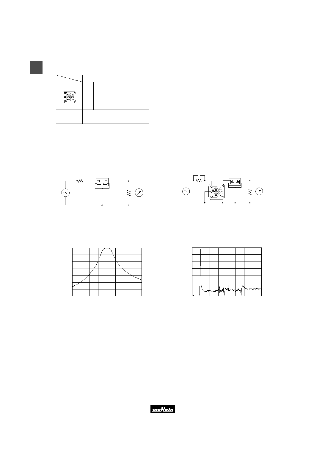
s Recommended IFT
(1)
(2)
S(3)
(4)S
(6)
Type
Item
Winding Specification
No load Qu
Tuning Capacitance
90
180pF
7
◊
7mm IFT
(1)--(2)
(2)--(3)
(4)--(6)
85T
67T
23T
(Bottom view)
65
180pF
5
◊
5mm IFT
(1)--(2)
(2)--(3)
(4)--(6)
84T
98T
33T
∑ Maching of CERAFIL
r
PFWLA series with IFT is decided by the IFT secondary side
impedance, |Z2|. Set the |Z2| at about 4.2k
.
s Test Circuit (CERAFILr Only)
PFWCC Series
(1)
(2)
(4)
(3)
S.S.G.
(Rg=50
)
3k
RF
Voltmeter
3
k
s Test Circuit (CERAFILr with IFT)
PFWCC Series
S.S.G.
(Rg=50
)
7pF
300k
RF
Voltmeter
3
k
IFT
(1)
(4)
(1)
(3)
(2)
(2)
(3)
(4)
(6)
s Selectivity Characteristics(Freq. Char. with IFT)
IFT+PFWCC450KS2A-B0
70
60
50
40
30
20
10
0
Frequency (kHz)
A
t
t
e
n
u
a
t
i
o
n
(
d
B
)
430
440
450
460
470
s Sprious Characteristics(Freq. Char. with IFT)
IFT+PFWCC450KS2A-B0
70
60
50
40
30
20
10
0
0.000
1.000
2.000
3.000
4.000
Frequency (kHz)
A
t
t
e
n
u
a
t
i
o
n
(
d
B
)