
1
1
!
Note
∑ Please read rating and
!
CAUTION (for storage, operating, rating, soldering, mounting and handling) in this catalog to prevent smoking and/or burning, etc.
∑ This catalog has only typical specifications because there is no space for detailed specifications. Therefore, please approve our product specifications or transact the approval sheet for product specifications before ordering.
Chip Multilayer Delay Lines
Chip Multilayer Delay Lines
This Delay Line was developed by applying ceramic
multilayering and hole technology. It consists of
copper line and low dielectric constant material and
incorporates metal shields. LDH series are very small
and made for use at high frequencies.
s Features
1. High stability at high frequency (2GHz)
2. Small, thin and light, utilizing multilayer
construction
3. Metal shield is built inside chip.
4. Reflow solderable
5. Supplied on tape
(in mm)
All the technical data and information contained herein are subject
to change without prior notice.
(3)
(4)
(8)
(2)
(1)
(5)
(6)
(7)
3.2
±
0.2
0.45
±
0.15
0.35
±
0.2
0.5
±
0.1
1.0
±
0.1
1.1
±
0.2
1.60
±
0.2
0.25+0.1/-0.15
0.5
±
0.1
0.25+0.1/-0.15
(1)(3)(5)(7) : NC
(2)(6) : GND
(4)(8) : IN/OUT
Terminal of "NC" should not be fixed to any pattern.
LDH31 Series
3.2
±
0.2
1.5
±
0.15
(3)
(2)
(1)
(1)(3)(5)(7) : NC
(2)(6) : GND
(4) : IN/OUT
(8) : IN/OUT
(in mm)
(5)
(4)
(8)
0.7
±
0.2
0.4
±
0.2
(6)
(7)
0.4
±
0.2
0.1min.
0.55
±
0.15
0.45
±
0.15 1.0
±
0.2
2.5
±
0.2
Terminal of "NC" should not be fixed
to any pattern.
All the technical data and information
contained herein are subject to
change without prior notice.
LDH32 Series
All the technical data and information contained herein are
subject to change without prior notice.
(in mm)
Directional
Input Mark
(7)
(8)
2.0
±
0.1
0.6
±
0.1
2.2
±
0.1
0.3
±
0.2
0.1
±
0.1
0.4
±
0.2
0.35
±
0.10
1.27
±
0.10
4.5
±
0.2
1.1
±
0.2
3.2
±
0.2
(1)
(2)
(3)
(6)
(5)
(4)
: GND
: IN/OUT
(1)(3)(4)(5)(7)(8)
(2)(6)
LDH43 Series
(in mm)
5.0
±
0.3
1.1≠3.1
0.35
±
0.2
4.0
±
0.3
0.3
±
0.2
0.8
±
0.2
1.27
±
0.2
1.27
±
0.2
0.3max.
0.4
±
0.2
: IN / OUT
: GND
(1)
(1)
(2)
(2)
(3)
(3)
(6)
(6)
(5)
(5)
(4)
(4)
LDH54 Series
6.3
±
0.3
2.5 max.
0.5 min.
0.5 min.
1.27
±
0.2
0.3 max.
0.6 min. 0.4 min.
0.55
±
0.3
0.3
±
0.2
5.0
±
0.3
(1) (2) (3) (4)
(8) (7) (6) (5)
(1)
(2)(3)(4)
(6)(7)(8)
(5)
(in mm)
: IN / OUT
: GND
LDH65 Series
10.0
±
0.3
3.7 max.
0.4 min.
0.8 min.
2.54
±
0.2
0.3 max.
0.5 min. 0.4 min.
0.55
±
0.3
0.9
±
0.3
6.3
±
0.3
(1) (2) (3) (4)
(9) (8) (7) (6)
(1)
(2)(3)(4)
(5)(7)(8)
(6)
(in mm)
: IN / OUT
: GND
(10)
(5)
(9)(10)
3.0
±
0.3
2.1
±
0.3
1.4
±
0.3
LDHA2 Series
Please read rating and
!
CAUTION (for storage, operating, rating, soldering, mounting and handling) in this PDF catalog to prevent smoking and/or burning, etc.
This catalog has only typical specifications. Therefore, you are requested to approve our product specifications or to transact the approval sheet for product specificaions before ordering.
!
Note
N91E7.pdf 03.5.13
Cat.No.N91E-7

2
1
!
Note
∑ Please read rating and
!
CAUTION (for storage, operating, rating, soldering, mounting and handling) in this catalog to prevent smoking and/or burning, etc.
∑ This catalog has only typical specifications because there is no space for detailed specifications. Therefore, please approve our product specifications or transact the approval sheet for product specifications before ordering.
Part Number
Delay Time
(ns)
Impedance
(ohm)
Rising Time
(ns)
Insulation Resistance
(M ohm)
Rated Current
(mA)
LDH311N00LAC-810
0.1
±
15%
50 (Nominal)
0.8 max.
100 min.
50
LDH311N50LAC-810
1.5
±
15%
50 (Nominal)
1.0 max.
100 min.
50
LDH312N00LAC-810
2.0
±
15%
50 (Nominal)
1.5 max.
100 min.
50
LDH321N00LAC-800
1.0
±
15%
50 (Nominal)
0.8 max.
100 min.
50
LDH321N50LAC-800
1.5
±
15%
50 (Nominal)
1.0 max.
100 min.
50
LDH322N00LAC-800
2.0
±
15%
50 (Nominal)
1.5 max.
100 min.
50
LDH322N50LAC-800
2.5
±
15%
50 (Nominal)
1.8 max.
100 min.
50
LDH323N00LAC-800
3.0
±
15%
50 (Nominal)
2.0 max.
100 min.
50
LDH43050PAAA-830
50.0 ns
±
11.0ns (at 10.0GHz)
50 (at 10.0GHz) (Nominal)
-
100 min.
50
LDH43060PAAA-830
60.0 ps
±
11.0ps (at 10.0GHz)
50 (at 10.0GHz) (Nominal)
-
100 min.
50
LDH43070PAAA-830
70.0 ps
±
11.0ps (at 10.0GHz)
50 (at 10.0GHz) (Nominal)
-
100 min.
50
LDH43080PAAA-830
80.0 ps
±
11.0ps (at 10.0GHz)
50 (at 10.0GHz) (Nominal)
-
100 min.
50
LDH43090PAAA-830
90.0 ps
±
11.0ps (at 10.0GHz)
50 (at 10.0GHz) (Nominal)
-
100 min.
50
LDH43100PAAA-830
100.0 ps
±
11.0% (at 10.0GHz)
50 (at 10.0GHz) (Nominal)
-
100 min.
50
LDH43110PKAA-830
110.0 ps
±
11.0% (at 10.0GHz)
50 (at 10.0GHz) (Nominal)
-
100 min.
50
LDH43120PKAA-830
120.0 ps
±
11.0% (at 10.0GHz)
50 (at 10.0GHz) (Nominal)
-
100 min.
50
LDH43130PKAA-830
130.0 ps
±
11.0% (at 10.0GHz)
50 (at 10.0GHz) (Nominal)
-
100 min.
50
LDH43140PKAA-830
140.0 ps
±
11.0% (at 10.0GHz)
50 (at 10.0GHz) (Nominal)
-
100 min.
50
LDH43150PKAA-830
150.0 ps
±
11.0% (at 10.0GHz)
50 (at 10.0GHz) (Nominal)
-
100 min.
50
LDH54100PAAA-600
0.1
±
0.05ns
50
±
7 (at 100MHz)
0.15 max.
100 min.
50
LDH54200PAAA-600
0.2
±
0.05ns
50
±
7 (at 100MHz)
0.15 max.
100 min.
50
LDH54300PAAA-600
0.3
±
0.05ns
50
±
7 (at 100MHz)
0.15 max.
100 min.
50
LDH54400PAAA-600
0.4
±
0.05ns
50
±
7 (at 100MHz)
0.15 max.
100 min.
50
LDH54500PAAA-600
0.5
±
0.05ns
50
±
7 (at 100MHz)
0.15 max.
100 min.
50
LDH54600PBAA-600
0.6
±
0.1ns
50
±
7 (at 100MHz)
0.3 max.
100 min.
50
LDH54700PBAA-600
0.7
±
0.1ns
50
±
7 (at 100MHz)
0.3 max.
100 min.
50
LDH54800PBAA-600
0.8
±
0.1ns
50
±
7 (at 100MHz)
0.3 max.
100 min.
50
LDH54900PBAA-600
0.9
±
0.1ns
50
±
7 (at 100MHz)
0.3 max.
100 min.
50
LDH541N00BAA-600
1.0
±
0.1ns
50
±
7 (at 100MHz)
0.3 max.
100 min.
50
LDH541N50BAA-600
1.5
±
0.1ns
50
±
7 (at 100MHz)
0.5 max.
100 min.
50
LDH542N00BAA-600
2.0
±
0.1ns
50
±
7 (at 100MHz)
0.5 max.
100 min.
50
LDH542N50BAA-600
2.5
±
0.1ns
50
±
7 (at 100MHz)
0.5 max.
100 min.
50
LDH543N00KAB-700
3.0
±
0.3ns
75 (Nominal)
2.0 max.
100 min.
50
LDH544N00KAB-700
4.0
±
0.4ns
75 (Nominal)
2.5 max.
100 min.
50
LDH545N00KAB-700
5.0
±
0.5ns
75 (Nominal)
2.5 max.
100 min.
50
LDH546N00KAB-700
6.0
±
0.6ns
75 (Nominal)
3.0 max.
100 min.
50
LDH547N00KAB-700
7.0
±
0.7ns
75 (Nominal)
3.5 max.
100 min.
50
LDH548N00KAB-700
8.0
±
0.8ns
75 (Nominal)
3.5 max.
100 min.
50
LDH549N00KAB-700
9.0
±
0.9ns
75 (Nominal)
4.0 max.
100 min.
50
LDH5410N0KAB-700
10.0
±
1.0ns
75 (Nominal)
4.5 max.
100 min.
50
LDH65100PAAA-400
0.1
±
0.05ns
50
±
5 (at 100MHz)
0.10 max.
100 min.
100
LDH65200PAAA-400
0.2
±
0.05ns
50
±
5 (at 100MHz)
0.10 max.
100 min.
100
LDH65300PAAA-400
0.3
±
0.05ns
50
±
5 (at 100MHz)
0.15 max.
100 min.
100
LDH65400PAAA-400
0.4
±
0.05ns
50
±
5 (at 100MHz)
0.15 max.
100 min.
100
LDH65500PAAA-400
0.5
±
0.05ns
50
±
5 (at 100MHz)
0.15 max.
100 min.
100
LDH65600PBAA-400
0.6
±
0.1ns
50
±
5 (at 100MHz)
0.15 max.
100 min.
100
LDH65700PBAA-400
0.7
±
0.1ns
50
±
5 (at 100MHz)
0.20 max.
100 min.
100
LDH65800PBAA-400
0.8
±
0.1ns
50
±
5 (at 100MHz)
0.20 max.
100 min.
100
LDH65900PBAA-400
0.9
±
0.1ns
50
±
5 (at 100MHz)
0.20 max.
100 min.
100
LDH651N00BAA-400
1.0
±
0.1ns
50
±
5 (at 100MHz)
0.20 max.
100 min.
100
LDHA2500PAAA-300
0.5
±
0.05ns
50
±
5 (at 100MHz)
0.15 max.
100 min.
100
LDHA21N00BAA-300
1.0
±
0.1ns
50
±
5 (at 100MHz)
0.20 max.
100 min.
100
LDHA21N50BAA-300
1.5
±
0.1ns
50
±
5 (at 100MHz)
0.30 max.
100 min.
100
LDHA22N00BAA-300
2.0
±
0.1ns
50
±
5 (at 100MHz)
0.40 max.
100 min.
100
LDHA22N50BAA-300
2.5
±
0.1ns
50
±
5 (at 100MHz)
0.40 max.
100 min.
100
LDHA23N00BAA-300
3.0
±
0.1ns
50
±
10 (at 100MHz)
0.75 max.
100 min.
100
LDHA24N00BAA-300
4.0
±
0.1ns
50
±
10 (at 100MHz)
1.00 max.
100 min.
100
Continued on the following page.
Please read rating and
!
CAUTION (for storage, operating, rating, soldering, mounting and handling) in this PDF catalog to prevent smoking and/or burning, etc.
This catalog has only typical specifications. Therefore, you are requested to approve our product specifications or to transact the approval sheet for product specificaions before ordering.
!
Note
N91E7.pdf 03.5.13

3
1
!
Note
∑ Please read rating and
!
CAUTION (for storage, operating, rating, soldering, mounting and handling) in this catalog to prevent smoking and/or burning, etc.
∑ This catalog has only typical specifications because there is no space for detailed specifications. Therefore, please approve our product specifications or transact the approval sheet for product specifications before ordering.
Part Number
Delay Time
(ns)
Impedance
(ohm)
Rising Time
(ns)
Insulation Resistance
(M ohm)
Rated Current
(mA)
Continued from the preceding page.
LDHA25N00BAA-300
5.0
±
0.1ns
50
±
10 (at 100MHz)
1.25 max.
100 min.
100
LDHA26N00CAA-300
6.0
±
0.2ns
50
±
10 (at 100MHz)
1.50 max.
100 min.
100
LDHA27N00CAA-300
7.0
±
0.2ns
50
±
10 (at 100MHz)
1.75 max.
100 min.
100
LDHA28N00CAA-300
8.0
±
0.2ns
50
±
10 (at 100MHz)
2.00 max.
100 min.
100
LDHA29N00CAA-300
9.0
±
0.2ns
50
±
10 (at 100MHz)
2.25 max.
100 min.
100
LDHA210N0CAA-300
10.0
±
0.2ns
50
±
10 (at 100MHz)
2.50 max.
100 min.
100
Operating Temperature Range : -40
∞
C to +85
∞
C
s Group Delay Time
Test sample: LDH65500PAAA-400
G
.
D
.
T
.
(
n
s
e
c
.
)
3G
0.4
0.5
1G
500M
100M
Frequency (Hz)
0.3
0.2
0.1
0.8
0.9
0.7
0.6
s Pulse Response
Test sample: LDH65500PAAA-400
V
o
l
t
a
g
e
(
m
V
)
200
150
100
50
0
0
0.5
1
1.5
2
2.5
3
Time (nsec.)
Output Wave Form
Input Wave Form
s Impedance
Test sample: LDH65500PAAA-400
Frequency Range : 100MHz to 3GHz (Smith Chart)
s Return Loss
Test sample: LDH65500PAAA-400
Frequency Range
3GHz
100MHz
50dB
0
-50
s Insertion Loss
Test sample: LDH65500PAAA-400
I
n
s
e
r
t
i
o
n
L
o
s
s
(
d
B
)
3G
-1
0
1G
500M
100M
Frequency (Hz)
-2
-3
-4
Please read rating and
!
CAUTION (for storage, operating, rating, soldering, mounting and handling) in this PDF catalog to prevent smoking and/or burning, etc.
This catalog has only typical specifications. Therefore, you are requested to approve our product specifications or to transact the approval sheet for product specificaions before ordering.
!
Note
N91E7.pdf 03.5.13

Soldering and Mounting
4
1
!
Note
∑ Please read rating and
!
CAUTION (for storage, operating, rating, soldering, mounting and handling) in this catalog to prevent smoking and/or burning, etc.
∑ This catalog has only typical specifications because there is no space for detailed specifications. Therefore, please approve our product specifications or transact the approval sheet for product specifications before ordering.
s Standard Land Dimensions
LDH31 Series
(in mm)
All the technical data and Information
contained herein are subject
to change without prior notice.
Line width to be designd to match 50ohm
characteristic impedance, depending
on PCB material and thickness.
0
.
7
0
0
.
5
5
0
.
4
5
0
.
8
0
0
.
6
5
1.00
0.60
1.00
1.05
0.30
2.60
0.70
0.30
0.25
0.45
0
.
6
0
1
.
0
0
1
.
0
0
1
.
0
0
Land
Solder resist
No pattern Solder resist
LDH32 Series
2.2
1.5
1
.
0
1.5
0
.
8
0
.
9
0
.
3
0
.
3
0
.
2
1
.
5
1.0
1.25
0.7
0.3
0.7
0.05
0.4
Land
(in mm)
Solder resist
No pattern
Solder resist
Line width to be designed to match 50
characteristic impedance,
depending on PCB material and thickness.
All the technical data and Information contained
herein are subject to change without prior notice.
LDH43 Series
All the technical data and information contained herein are subject to change without prior notice.
(in mm)
Land
0.6
0.6
1
.
4
1
.
4
2
.
2
1.0
1.27
2
.
4
3.5
LDH54 Series
Land
(in mm)
Solder resist
No pattern
Solder resist
Line width to be designed to match 50ohm characteristic
impedance, depending on PCB material and thickness.
0.37
0.37
0.9
0.9
0.9
3
.
0
6
.
0
LDH65 Series
2.17
2.91
0.37
4.71
Line width to be designed to match 50
characteristic
impedance, depending on PCB material and thickness.
(in mm)
4
.
0
7
.
0
No Pattern
Solder Resist
Land
Solder Resist
*
*
*
LDHA2 Series
(in mm)
No Pattern
Solder Resist
Land
Solder Resist
3.74
6.6
11.0
8.82
1.34
3
.
3
3
.
9
8
.
3
6.42
Line width to be designed to match 50
characteristic
impedance, depending on PCB material and thickness.
*
*
*
Please read rating and
!
CAUTION (for storage, operating, rating, soldering, mounting and handling) in this PDF catalog to prevent smoking and/or burning, etc.
This catalog has only typical specifications. Therefore, you are requested to approve our product specifications or to transact the approval sheet for product specificaions before ordering.
!
Note
N91E7.pdf 03.5.13

Packaging
5
1
!
Note
∑ Please read rating and
!
CAUTION (for storage, operating, rating, soldering, mounting and handling) in this catalog to prevent smoking and/or burning, etc.
∑ This catalog has only typical specifications because there is no space for detailed specifications. Therefore, please approve our product specifications or transact the approval sheet for product specifications before ordering.
s Minimum Quantity
Part Number
Dimensions (mm)
Minimum Quantity
L
W
T
ÿ180mm Reel
ÿ330mm Reel
500
3000
2000
1000 *
500
LDH31
3.2
1.6
1.1
LDH32
3.2
2.5
1.5
1000
LDH43
4.5
3.2
1.1
LDH54
5.0
4.0
1.1-3.1
LDH65
6.3
5.0
2.5
LDHA2
10.0
6.3
3.7
* 500pcs. for LDH542N0 and LDH542N5.
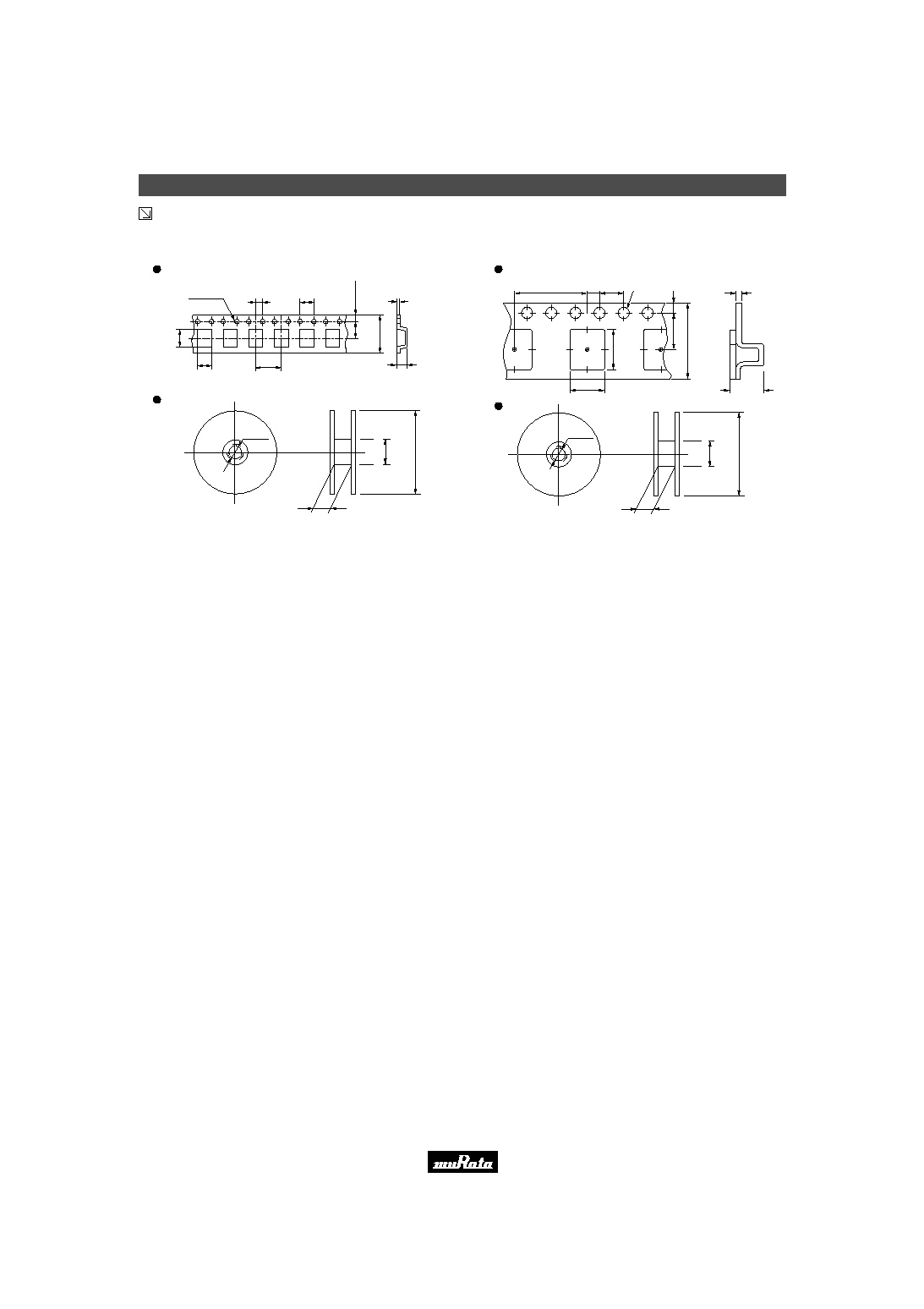
s Dimensions of Taping
LDH31 Series
(in mm)
Plastic Tape
Reel
2.0
±
0.1
4.0
±
0.1
1.75
±
0.1
3.5
±
0.05
8.0
±
0.2
3.5
±
0.2
1.9
±
0.2
4.0
±
0.1
0.25
±
0.1
1.8 max.
¯1.5
+0.1
-0
8.5
±
1.0
178
±
2.0
60 min.
¯13
±
0.5
LDH32 Series
Plastic Tape
Reel
2.0
±
0.1
4.0
±
0.1
1.75
±
0.1
3.5
±
0.1
8.0
±
0.3
3.5
±
0.2
2.8
±
0.2
4.0
±
0.1
0.25
±
0.1
2.3 max.
¯1.5
+0.1
-0
8.5
±
1.0
178
±
2.0
60 min.
¯13
±
0.5
(in mm)
LDH43 Series
¯13
±
0.5
12.5
±
1.5
178
±
2.0
60 min.
2.0
±
0.1
4.0
±
0.1
1.75
±
0.1
5.5
±
0.1
12.0
±
0.3
4.9 (Typical value)
3.6 (Typical value)
8.0
±
0.1
0.3
±
0.1
1.8 max.
¯1.5
+0.1
-0
(in mm)
Plastic Tape
Reel
LDH54 Series
(in mm)
¯13
±
0.5
12.5
±
1.5
178
±
2.0
60 min.
Plastic Tape
Reel
2.0
±
0.1
4.0
±
0.1
1.75
±
0.1
5.5
±
0.1
12.0
±
0.3
5.9 (Typical value)
4.4 (Typical value)
8.0
±
0.1
0.4
±
0.1
3.8 max.
¯1.5
+0.1
-0
Continued on the following page.
Please read rating and
!
CAUTION (for storage, operating, rating, soldering, mounting and handling) in this PDF catalog to prevent smoking and/or burning, etc.
This catalog has only typical specifications. Therefore, you are requested to approve our product specifications or to transact the approval sheet for product specificaions before ordering.
!
Note
N91E7.pdf 03.5.13
Packaging
6
1
!
Note
∑ Please read rating and
!
CAUTION (for storage, operating, rating, soldering, mounting and handling) in this catalog to prevent smoking and/or burning, etc.
∑ This catalog has only typical specifications because there is no space for detailed specifications. Therefore, please approve our product specifications or transact the approval sheet for product specifications before ordering.
Continued from the preceding page.
s Dimensions of Taping
LDH65 Series
(in mm)
¯13
±
0.5
12.5
±
1.5
1
7
8
±
2
.
0
6
0
m
i
n
.
Plastic Tape
Reel
2.0
±
0.1
4.0
±
0.1
1
.
7
5
±
0
.
1
5
.
5
±
0
.
1
1
2
.
0
±
0
.
3
6
.
9
(
T
y
p
i
c
a
l
v
a
l
u
e
)
5.6 (Typical value)
8.0
±
0.1
0.3
±
0.1
2.9 max.
¯1.5
+0.1
-0
LDHA2 Series
(in mm)
Plastic Tape
Reel
12.0
±
0.1
2.0
±
0.1
4.0
±
0.1
¯1.5
+0.1
-0.0
1
.
7
5
±
0
.
1
7
.
5
±
0
.
1
1
6
.
0
±
0
.
3
1
0
.
6
(
T
y
p
i
c
a
l
v
a
l
u
e
)
6.9 (Typical value)
0.4
±
0.1
4.3 max.
17.5
±
1.5
1
0
0
m
i
n
.
3
3
0
±
2
.
0
¯13
±
0.5
Please read rating and
!
CAUTION (for storage, operating, rating, soldering, mounting and handling) in this PDF catalog to prevent smoking and/or burning, etc.
This catalog has only typical specifications. Therefore, you are requested to approve our product specifications or to transact the approval sheet for product specificaions before ordering.
!
Note
N91E7.pdf 03.5.13

Notice
7
1
!
Note
∑ Please read rating and
!
CAUTION (for storage, operating, rating, soldering, mounting and handling) in this catalog to prevent smoking and/or burning, etc.
∑ This catalog has only typical specifications because there is no space for detailed specifications. Therefore, please approve our product specifications or transact the approval sheet for product specifications before ordering.
s Notice (Storage and Operating Condition)
o
Store products where the ambient temperature is 15 to
35
∞
C and the relative humidity is 45 to 75% RH.
(Packing materials, in particular, may be deformed at
temperatures over 40
∞
C.).
o
Bulk packed chip components should be used as soon as
the seal is opened, thus preventing the solderability from
deteriorating. The remaining unused components should
be put in the original bag and resealed, or stored in a
desiccator containing a desiccating agent.
o
Store products in non-corrosive gas (Cl
2
, NH
3
, SO
2
, Nox,
etc.).
o
Stored products should be used within 6 months of
receipt. Solderability should be verified if this period is
exceeded.
To avoid damaging the solderability of the external
electrodes, be sure to observe the following points.
s Notice (Rating)
Products should be used in an input power capacity as
specified in this catalog.
Consult with Murata beforehand if a different input
power capacity range is required.
Please read rating and
!
CAUTION (for storage, operating, rating, soldering, mounting and handling) in this PDF catalog to prevent smoking and/or burning, etc.
This catalog has only typical specifications. Therefore, you are requested to approve our product specifications or to transact the approval sheet for product specificaions before ordering.
!
Note
N91E7.pdf 03.5.13

Notice
8
1
!
Note
∑ Please read rating and
!
CAUTION (for storage, operating, rating, soldering, mounting and handling) in this catalog to prevent smoking and/or burning, etc.
∑ This catalog has only typical specifications because there is no space for detailed specifications. Therefore, please approve our product specifications or transact the approval sheet for product specifications before ordering.
s Notice (Soldering and Mounting)
1. Standard PCB Design (Land Pattern and Dimensions):
All the ground terminals should be connected to the
ground patterns. Please refer to specifications for
standard land dimensions.
The recommended land pattern and dimensions is as
Murata's standard. The characteristics of products may
vary depending on the pattern drawing method,
grounding method, land dimensions and the PCB
material and thickness. Therefore, be sure to verify the
characteristics in the actual set. When using non-
standard lands, contact Murata beforehand.
o
Diameter of iron-tip : f3.0 mm max.
o
Do not allow the iron-tip to directly touch the ceramic
element.
Use rosin type flux or weakly active flux with a chlorine
content of 0.2 wt % or less.
Use eutectic crystal solder.
Amount of Solder Paste:
o
Ensure that solder is applied smoothly to a minimum
height of 0.2 to 0.5 mm at the end surface of the external
electrodes. If too much or little solder is applied, there is
high possibility that the mechanical strength will be
insufficient, creating the variation of characteristics.
2. Soldering Conditions:
Carefully perform preheating so that the temperature
difference (
T) between the solder and products surface
should be in the following range. When products are
immersed in solvent after mounting, pay special attention
to maintain the temperature difference within 100
∞
C.
Soldering must be carried out by the above mentioned
conditions to prevent products from damage.
If other soldering conditions exist, please contact Murata
before use.
o
Soldering iron method conditions are indicated below.
Soldering iron method
Soldering method
Temperature
T
V
130
∞
C
Reflow method
Soldering iron wattage
Nichrome heater
V
30W
V
280
∞
C
Ceramics heater
V
18W
V
250
∞
C
Temperature of iron-tip
Kind of iron
Item
T
e
m
p
e
r
a
t
u
r
e
(
∞
C
)
220--230
∞
C
within 10sec.
Pre-heating
200
∞
C
60sec. min.
within 120sec.
Time (sec.)
T
within 20--40sec.
Reflow soldering standard conditions (Example)
s Notice (Handling)
1. Be careful in handling or transporting products
because excessive stress or mechanical shock may
break products due to the nature of ceramics
structure.
2. Handle with care. If products are cracked or have
damaged terminals, their characteristics may
change.
Do not touch products with bare hands. Poor
solderability may result.
3. Notice for Chip Placement
When the products are placed on the PCB, they may
be stressed and broken by uneven forces from a
wornout chucking locator claw or suction device.
To prevent damage to products, be sure to follow
the maintenance specifications for the chip placer.
Be aware that mechanical chucking may damage
products when positioning them on the PCB.
Please read rating and
!
CAUTION (for storage, operating, rating, soldering, mounting and handling) in this PDF catalog to prevent smoking and/or burning, etc.
This catalog has only typical specifications. Therefore, you are requested to approve our product specifications or to transact the approval sheet for product specificaions before ordering.
!
Note
N91E7.pdf 03.5.13

Notice
9
1
!
Note
∑ Please read rating and
!
CAUTION (for storage, operating, rating, soldering, mounting and handling) in this catalog to prevent smoking and/or burning, etc.
∑ This catalog has only typical specifications because there is no space for detailed specifications. Therefore, please approve our product specifications or transact the approval sheet for product specifications before ordering.
s Notice (Other)
1. Cleaning Conditions:
The total cleaning time of soaking, ultrasonic and steam
methods should be within 5 minutes.
Consult with Murata concerning the cleaning solvent. In
order to totally abolish ODC (Freon, Trichrolethan),
Murata has carried out testing on non-cleaning and
water-cleaning solvents (water-soluble flux, water-soluble
cream solder, water-based cleaning solvent). Therefore,
be sure to contact Murata beforehand for details when
applying any of the above mentioned cleaning fluids.
If the ultrasonic output power is too high, the PCB may
resonate and products mounted on the PCB may be
damaged. The ultrasonic cleaning conditions may
change depending on the size of the vessel and the size
of the PCB. Contact Murata regarding conditions other
than those stated above.
Be sure to completely dry products immediately after
cleaning.
2. Operational Environment Conditions:
Products are designed to work for electronic products
under normal environmental conditions (ambient
temperature, humidity and pressure). However, if
products are used under the following circumstances, it
may damage products and leakage of electricity and
abnormal temperature may occur.
- In an atmosphere containing corrosive gas ( Cl
2
, NH
3
,
SO
x
, NO
x
etc.)
- In an atmosphere containing combustible and volatile
gases
- Dusty conditions
- Direct sunlight
- Wet conditions
- High humidity locations
- Freezing conditions
If products could be used under the preceding conditions,
consult with Murata before actual use. Be sure to
completely dry products immediately after cleaning.
The ultrasonic cleaning conditions are indicated below :
Frequency
Power
50 - 60 kHz
20 W per liter max.
Temperature
40 deg.C max.
Please read rating and
!
CAUTION (for storage, operating, rating, soldering, mounting and handling) in this PDF catalog to prevent smoking and/or burning, etc.
This catalog has only typical specifications. Therefore, you are requested to approve our product specifications or to transact the approval sheet for product specificaions before ordering.
!
Note
N91E7.pdf 03.5.13
10
!
Note
∑ Please read rating and
!
CAUTION (for storage, operating, rating, soldering, mounting and handling) in this catalog to prevent smoking and/or burning, etc.
∑ This catalog has only typical specifications because there is no space for detailed specifications. Therefore, please approve our product specifications or transact the approval sheet for product specifications before ordering.
(Part Number)
Chip Multilayer Delay Lines
iIndividual Specification Code (2)
eDimension (LgW)
Code
2.00g1.25mm
3.20g1.60mm
3.20g2.50mm
4.50g3.20mm
5.00g4.00mm
6.30g5.00mm
10.0g6.3mm
Dimension (LgW)
0805
1206
1210
≠
≠
≠
≠
EIA
21
31
32
43
54
65
A2
qProduct ID
LD
Chip Multilayer Devices
Product ID
wFunction
Code
H
Delay Lines
Function
yIndividual Specification Code (1)
A
Standard
Code
rDelay Time
Three figures and a capital letter express the nominal value. If the
unit is "nano-second", a decimal point is expressed by the capital
letter "
N
". If the unit is "pico-second", the letter "
P
".
A hyphen (-), figures or letters express the specifications of other
characteristics.
uDesign
Code
A
A letter expresses identification
of design type for each function.
Design
tDelay Time Tolerance
A
B
C
K
L
±
0.05ns
±
0.1ns
±
0.2ns
±
10%
±
15%
Code
Delay Time Tolerance
Individual Specification Code (1)
t
A
y
A
u
A
q
LD
r
100P
e
65
w
H
i
-400
o
Part Numbering
Please read rating and
!
CAUTION (for storage, operating, rating, soldering, mounting and handling) in this PDF catalog to prevent smoking and/or burning, etc.
This catalog has only typical specifications. Therefore, you are requested to approve our product specifications or to transact the approval sheet for product specificaions before ordering.
!
Note
N91E7.pdf 03.5.13

Head Office
2-26-10, Tenjin Nagaokakyo-shi, Kyoto 617-8555, Japan Phone: 81-75-951-9111
International Division
3-29-12, Shibuya, Shibuya-ku, Tokyo 150-0002, Japan
Phone: 81-3-5469-6123 Fax: 81-3-5469-6155 E-mail: intl@murata.co.jp
http://www.murata.com/
Please read rating and
!
CAUTION (for storage, operating, rating, soldering, mounting and handling) in this PDF catalog to prevent smoking and/or burning, etc.
This catalog has only typical specifications. Therefore, you are requested to approve our product specifications or to transact the approval sheet for product specificaions before ordering.
!
Note
N91E7.pdf 03.5.13
Note:
1. Export Control
<
For customers outside Japan
>
Murata products should not be used or sold for use in the development, production, stockpiling or utilization of any conventional weapons or mass-destructive
weapons (nuclear weapons, chemical or biological weapons, or missiles), or any other weapons.
<
For customers in Japan
>
For products which are controlled items subject to the "Foreign Exchange and Foreign Trade Law" of Japan, the export license specified by the law is required
for export.
2. Please contact our sales representatives or product engineers before using the products in this catalog for the applications listed below, which require especially
high reliability for the prevention of defects which might directly damage to a third party's life, body or property, or when one of our products is intended for use
in applications other than those specified in this catalog.
q
Aircraft equipment
w
Aerospace equipment
e
Undersea equipment
r
Power plant equipment
t
Medical equipment
y
Transportation equipment (vehicles, trains, ships, etc.)
u
Traffic signal equipment
i
Disaster prevention / crime prevention equipment
o
Data-processing equipment
!0
Application of similar complexity and/or reliability requirements to the applications listed in the above
3. Product specifications in this catalog are as of September 2002. They are subject to change or our products in it may be discontinued without advance notice.
Please check with our sales representatives or product engineers before ordering. If there are any questions, please contact our sales representatives or
product engineers.
4. Please read rating and CAUTION (for storage, operating, rating, soldering, mounting and handling) in this catalog to prevent smoking and/or burning, etc.
5. This catalog has only typical specifications because there is no space for detailed specifications. Therefore, please approve our product specifications or
transact the approval sheet for product specifications before ordering.
6. Please note that unless otherwise specified, we shall assume no responsibility whatsoever for any conflict or dispute that may occur in connection with the effect
of our and/or a third party's intellectual property rights and other related rights in consideration of your use of our products and/or information described or
contained in our catalogs. In this connection, no representation shall be made to the effect that any third parties are authorized to use the rights mentioned
above under licenses without our consent.
7. No ozone depleting substances (ODS) under the Montreal Protocol are used in our manufacturing process.