 | –≠–ª–µ–∫—Ç—Ä–æ–Ω–Ω—ã–π –∫–æ–º–ø–æ–Ω–µ–Ω—Ç: MTD891 | –°–∫–∞—á–∞—Ç—å:  PDF PDF  ZIP ZIP |

Gigabit Network Interface Controller
MTD891
BLOCK DIAGRAM
GENERAL DESCRIPTION
FEATURES
Myson-Century Technology
USA:
4020 Moorpark Avenue Suite 115
San Jose, CA, 95117
Tel: 408-243-8388 Fax: 408-243-3188
Sales@myson.com.tw
www.myson.com.tw
www.century-semi.com
Rev.1.1 January 2002
page 1 of 35
Myson-Century Technology, Inc.
Taiwan:
No. 2, Industry East Rd. III,
Science-Based Industrial Park, Hsin-Chu, Taiwan
Tel: 886-3-5784866 Fax: 886-3-5784349
∑ Compliant with PCI bus interface v2.2.
∑ IEEE802.3 ,802.3u and 802.3z compliant.
∑ High performance with PCI bus master structure.
∑ Programmable PCI burst length for low CPU
utilization rate.
∑ Transmit packet queuing capability for higher
performance.
∑ Supports both full-duplex and half-duplex mode
operations.
∑ Supports both IEEE802.3x and XON/XOFF full
duplex flow control methods.
∑ Contains separate transmit and receive FIFOs.
∑ Supports Magic packet and Microsoft wake-up frame
filtering.
∑ Supports ACPI and PCI power management.
∑ Supports CardBus STSCHG pin and status changed
registers. The CIS can be stored in the EEPROM.
∑ Autoload EEPROM contents after power-on.
∑ Programmable EEPROM interface.
∑ Supports PCI 33/66 MHz.
∑ 128-pin PQFP package.
∑ Single 3.3V power supply.
The MTD891 is a highly integrated 10/100 /
1000Mbits ethernet controller for PCI interface. The
chip contains a PCI interface block, two large FIFOs (8
KBytes and 16 KBytes) for transmit and receive DMA,
IEEE802.3/802.3u/802.3z compliant MAC GMAC
interface for MII/GMII connection. In addition, the chip
has a built-in Wake-Up controller to perform ACPI
function, and is capable of sensing IEEE 802.3x frame
to support XON/XOFF flow control protocol. The chip
also supports a direct interface to 93C46/93C56
EEPROM for executing auto-configuration after system
reset. For CardBus application, the MTD891 supports
four status-changed registers, an interface for
accessing CIS which is stored in EEPROM and
STSCHG pin to reflect the general wake-up events.
REG File
EEPROM I/F
LED Control
TxMAC
Processor
RxMAC
Processor
TxFIFO
TxDMA
RxDMA
RxFIFO
PCI
I/F
MII
or
GMII
Signals
PCI AD
Bus
and
Control
Signals
Tx
GMII
/MII
I/F
Rx
GMII
/MII
I/F

MTD891
page 2 of 35
Myson-Century Technology
PIN CONNECTION DIAGRAM
64
63
62
61
60
59
58
57
56
55
54
53
52
51
50
49
48
47
46
45
44
43
42
41
40
39
103
104
105
106
107
108
109
110
111
112
113
114
115
116
117
118
119
120
121
122
123
124
125
126
127
128
10
2
10
1
10
0
99
98
97
96
95
94
93
92
91
90
89
88
87
86
85
84
83
82
81
80
79
78
77
76
75
74
73
72
71
70
69
68
67
66
65
1
2
3
4
5
6
7
8
9
10
11
12
13
14
15
16
17
18
19
20
21
22
23
24
25
26
27
28
29
30
31
32
33
34
35
36
37
38
RX
D6
RX
D7
IS
OLA
T
E
#
VDD
VSS
C
L
K
123
MD
C
MD
I
O
INT
_
IN#
INT
A
#
RST
#
VSS
_
C
PCI
C
L
K
VDD_
C
GNT
#
REQ#
PM
E
#
VSS
AD3
1
AD3
0
AD2
9
AD2
8
VDD
VSS
AD2
7
AD2
6
AD2
5
AD2
4
VSS
VSS_
M
VDD_
M
VDD
CEB3
#
IDS
E
L
AD2
3
AD2
2
AD2
1
VDD
VSS
VDD
TX
D
3
TX
D
4
TX
D
5
VSS_
M
VDD_
M
TX
D
6
TX
D
7
VDD
VSS
EECS
P
A
USE/
EESK
ACT
/
EE
DI
EEDO
WUP/
SCH
AD0
AD1
AD2
VSS_
M
VDD_
M
AD3
AD4
AD5
AD6
VDD
VDD_
M
VSS_
M
VSS
AD7
CBE0
#
AD8
AD9
VSS
TE
ST
VDD
AD1
0
AD1
1
TXD2
TXD1
TXD0
TXEN
VSS
GTXCLK
VDD
TXER
TXCLK
CRS
COL
RXER
VSS_C
VDD_C
VDD
RXCLK
VSS
RXDV
RXD0
RXD1
RXD2
RXD3
VDD
VSS
RXD4
RXD5
AD12
AD13
VDD
VSS
AD14
AD15
CEB1#
PAR
SERR#
PERR#
STOP#
DEVSEL#
TRDY#
VSS
VDD
IRDY#
FRAME#
CEB2#
AD16
VDD
VSS
AD17
AD18
AD19
AD20
VSS
MTD891
128-pin QFP
MTD891
page 3 of 35
Myson-Century Technology
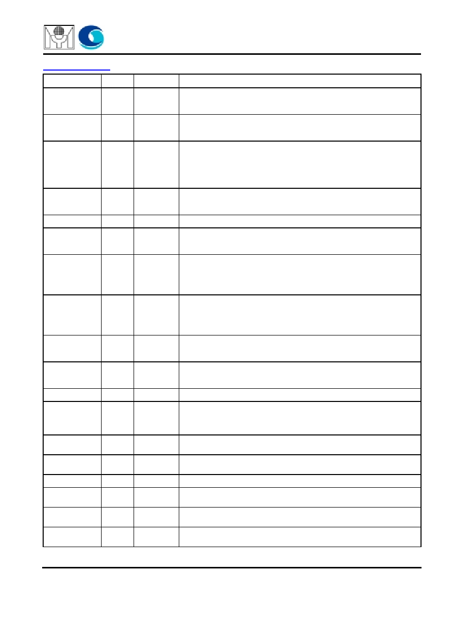
PIN DESCRIPTION
Name
I/O
Pin
Description
PCICLK
I
13
PCICLK provides timing reference for the MTD891 related PCI transactions.
All PCI signals except RST#,INTA# and PME# are sampled on the rising edge
of this clock.
RST#
I
11
When RST# is asserted, all output signals are put into tristate and all open
drain pins are floated. This signal is asynchronous to PCICLK and has to be
asserted for at least 10 active PCI clock cycles.
AD[31:0]
I/O
19-23, 25-28,
35-37, 40-43,
46, 59, 60,
63-66, 70, 71,
73, 78-81,
84-86
32-bit multiplexed address and data bus. A bus transaction is consisted of an
address phase followed by one or more data phases. During the first cycle in
which the FRAME# is asserted, the AD[31:0] represents the address bus,
after that it is considered as a data bus during subsequent cycles.
CBE#[3:0]
I/O
33, 47, 58, 72 4-bit multiplexed bus command and byte enables. During the address phase
transaction, CBE is considered as bus command. During the data phase
cycles, CBE represents the byte enable signals for PCI data bus.
IDSEL
I/O
34
Used as a chip select during access to the configuration registers.
FRAME#
I/O
48
Driven by the MTD891 to Indicate the start and duration of a transaction. The
FRAME# is deasserted when the master is ready to complete the final data
phase in the transaction.
IRDY#
I/O
49
During a write transaction, the current bus master asserts IRDY# to indicate
that valid data are being driven onto the PCI bus. During a read transaction,
this signal is asserted to indicate that the master is ready to accept data from
the selected target. Wait states are inserted until both IRDY# and TRDY# are
asserted.
TRDY#
I/O
52
During a read transaction, the target asserts TRDY# to indicate that valid data
are being driven onto the PCI bus. During a write transaction, this signal is
asserted to indicate that the target is ready to accept data. TRDY# is used in
conjunction with IRDY#. A data phase is completed on any clock when both
IRDY# and TRDY# are asserted.
DEVSEL#
I/O
53
Asserted by the MTD891 to indicate that the device has decoded the address
as the target of current access. As an input, DEVSEL# indicates whether any
device on the bus has been selected.
STOP#
I/O
54
Asserted by the MTD891 to disconnect any further transaction. As an input,
DEVSEL# indicates whether any device on the bus or bridge has terminated
the transaction.
INTA#
O/D
10
INTA# is an asynchronous signal that is used to request an interrupt.
PAR
I/O
57
Ensures even parity across AD[31:0] and CBE[3:0]. PAR is stable and valid
for one clock after the address phase. During the data phase, PAR is stable
and valid for one clock after either IRDY#(write transaction) or TRDY#(read
transaction) is asserted.
GNT#
I
15
Asserted by the PCI bus arbiter to indicate that the MTD891 has granted the
bus control authority.
REQ#
O/Z
16
Asserted by MTD891 to signal the bus arbiter that it needs the dedicated
access to the PCI bus.
PERR#
I/O
55
PERR# is asserted when a data parity error is detected.
PME#
O/D
17
An interrupt signal for the occurrence power management event. Asserted by
the MTD891 to request a change in the device or system power state.
COL
I
113
Collision signal. COL is asserted high when PHY detects a collision on the
medium. This signal is asynchronous to TXCK or RXCK.
RXDV
I
120
Receive data valid. RXDV is asserted high by PHY to indicate that the
incoming receive data RXD[3:0] is valid. This signal is synchronous to RXCK.

MTD891
page 4 of 35
Myson-Century Technology
TXCK
I
111
Transmit Clock. For MII mode, TXCK is a continuous clock that provides the
timing reference for the transfer of the TXD[3:0] and TXEN signals.
TXD[7:0]
O
94-95, 98-
100, 103-105
Transmit Data signals. TXD are driven by the MTD891 and transited
synchronously with respect to the TXCK. When in MII mode, only TXD[3:0]
are used.
TXEN
O
106
Transmit Data Enable. TXEN is driven by the MTD891 and transited
synchronously with respect to the TXCK.
RXCK
I
118
Receive Clock. RXCK is a continuous clock that provides the timing reference
for the transfer of the RXD[7:0], RXDV and RXER.
RXD[7:0]
I
121-124,
127-128, 1, 2
Receive Data signals. RXD are driven by PHY and transited synchronously
with respect to the RXCK. When in MII mode, only RXD[3:0] are used.
RXER
I
114
Receive Error signal. RXER is asserted high to indicate that a coding error is
detected by PHY. This signal is synchronous to RXCK.:0].
CRS
I
112
Carrier Sense signal. CRS is asserted by PHY when either the transmit or
receive medium is non-idle. This signal is asynchronous to TXCK or RX.
MDC
O
7
Management Data Clock. MDC is sourced by the MTD891 to control the
transfer of the MDIO data. A 1.5K pull-up resistor is required to connect to this
pin.
MDIO
I/O
8
Management Data Input/Output. A bi-directional data interface connected to
PHY. A 1.5K pull-up resistor is required to connect to this pin.
LED_ACT#/
EEDI
O
89
Activity LED. This signal drives the led light on when detecting activity on MII/
GMII interface. A 510 ohm pull-up resistor is required to connect to this pin.
Also, this pin acts as EEDI when EECS is asserted.
LED_PAUSE#/
EECK
O
90
Pause LED. This signal drives the led light on when detecting transmission is
paused under the condition of receiving a Xon frame. Also, this pin acts as
EECK when EECS is asserted.
EECS
I/O
91
Chip select signal for the external EEPROM. EEPROM is used to provide the
configuration data and Ethernet Address. A 100K pull-up resistor is connected
to this pin. Also, this pin has the jumper-setting function for selecting different
types of EEPROM. When connected with a pull-up resistor, the 93C56 are
chosen, otherwise, the 93C46 are selected as default.
WAKEUP/
STSCHG
O/Z
87
Wakeup Pin/CardBus STSCHG Pin. In PCI application, this pin is the Wakeup
pin to inform the host system of a happened wakeup event. In Card bus
application, this pin is used as the STSCHG pin to signal the system of any
status changed. This pin is enabled as STSCHG pin if the PME_Enable bit of
the power management control register is set and the FMR.GWAKE,
FMR.WAKE are both set.
ISOLATE#
I
3
ISOLATION pin. This pin should connect to the PCI stable power signal
(VDD). When PCI Bus is in B3 state, the power signal becomes de-asserted,
the ISOLATION pin is active however. Under this condition, the PCIRST# and
PCICLK are ignored and all the PCI output signals except PME# are isolated
from the PCI Bus.
INT_IN#
I
9
External Interrupt Input pin. The chip is able to accept one external interrupt
source and relay it to PCI interrupt.
VDD_M, VSS_M
P/G
31-30, 76-75,
83-82, 97-96
Digital 3.3V power and ground for internal SRAM.
Name
I/O
Pin
Description

MTD891
page 5 of 35
Myson-Century Technology
VDD
P
4, 14, 23, 32,
38, 45, 50,
62, 67, 77,
93, 101, 109,
16, 117, 125
Digital 3.3V power supply.
VSS
G
5, 12, 18, 24,
29, 39, 44,
51, 61, 60,
74, 92, 102,
107, 119, 126
Digital Ground.
Name
I/O
Pin
Description