 | –≠–ª–µ–∫—Ç—Ä–æ–Ω–Ω—ã–π –∫–æ–º–ø–æ–Ω–µ–Ω—Ç: AQH1223A | –°–∫–∞—á–∞—Ç—å:  PDF PDF  ZIP ZIP |
1
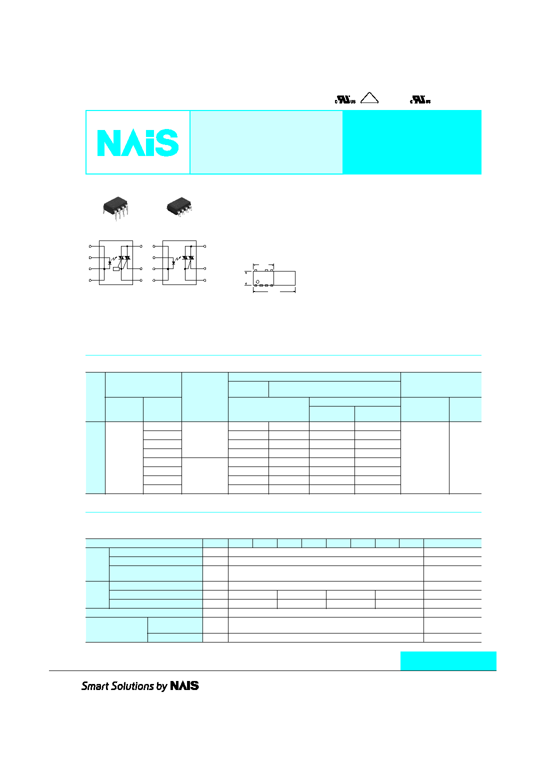
AQ-H SOLID STATE RELAY
ASCT1B272E '03.7
http://www.naisrelay.com/
New
AQ-H
RELAYS
Pending
VDE
(AQH1213, AQH1223, AQH2213, AQH2223) (AQH0213, AQH0223, AQH3213, AQH3223)
VDE
AQ-H SOLID STATE RELAY
1
8
≠
2
+
3
≠
4
≠
6
5
ZC
Zero-cross
circuit
1
8
≠
2
+
3
≠
4
≠
6
5
FEATURES
1. Compact DIP type SSR that's ideal
for AC load control
2. Supports 0.3 A, 0.6 A, 0.9 A and 1.2 A
ON-state RMS currents.
3. The 1.2 A type saves space with a
DIP 8-pin package. (Competitor only
provides a 16-pin type.)
4. Only ours handles both 100 and 200
V AC loads
This relay handles both voltages in a
single product. It is not necessary for
users that use both types to manage
separate part numbers.
5. High dielectric strength: 5,000 V AC
(between input and output)
6. Two types available: Zero-cross type
and Non-zero-cross type
TYPICAL APPLICATIONS
1. Home appliances (air conditioners,
microwave ovens, washing machines,
personal hygiene systems,
refrigerators, fan heaters, inductive
heating cooker, and water heaters,
etc.)
2. Industrial equipment market.
6.4
.252
DIP8
DIP16
(mm
inch
)
19.82
.780
9.78
.385
TYPES
*Indicate the repetitive peak OFF-state voltage and ON-state RMS current: peak AC.
Note: For space reasons, the SMD terminal shape indicator "A" and the package type indicator "X" and "Z" are omitted from the seal.
Type
Output rating*
Type
Part No.
Packing quantity
Through hole
terminal
Surface-mount terminal
Repetitive
peak OFF-
state voltage
ON-state
RMS current
Tube packing style
Tape and reel packing style
Tube
Tape and
reel
Picked from the
1/2/3/4-pin side
Picked from the
5/6/8-pin side
AC
type
600 V
0.3 A
Zero-cross
AQH0213
AQH0213A
AQH0213AX
AQH0213AZ
1 tube contains
40 pcs.
1 batch contains
400 pcs.
1,000 pcs.
0.6 A
AQH1213
AQH1213A
AQH1213AX
AQH1213AZ
0.9 A
AQH2213
AQH2213A
AQH2213AX
AQH2213AZ
1.2 A
AQH3213
AQH3213A
AQH3213AX
AQH3213AZ
0.3 A
Non zero-cross
AQH0223
AQH0223A
AQH0223AX
AQH0223AZ
0.6 A
AQH1223
AQH1223A
AQH1223AX
AQH1223AZ
0.9 A
AQH2223
AQH2223A
AQH2223AX
AQH2223AZ
1.2 A
AQH3223
AQH3223A
AQH3223AX
AQH3223AZ
RATING
1. Absolute maximum ratings
(Ambient temperature: 25
∞
C
77
∞
F
)
Item
Symbol
AQH0213 AQH0223 AQH1213 AQH1223 AQH2213 AQH2223 AQH3213 AQH3223
Remarks
Input
LED forward current
I
F
50 mA
LED reverse voltage
V
R
6 V
Peak forward current
I
FP
1 A
f = 100 Hz,
Duty Ratio = 0.1%
Output
Repetitive peak OFF-state votage
V
DRM
600 V
ON-state RMS current
IT
(RMS)
0.3 A
0.6 A
0.9 A
1.2 A
Non-repetitive surge current
I
TSM
3 A
6 A
9 A
12 A
60Hz, 1 cycle
I/O isolation voltage
V
iso
5,000 V AC
Temperature limits
Operating
T
opr
≠30
∞
C to +85
∞
C
≠22
∞
F to +185
∞
F
Non-condensing at
low temperatures
Storage
T
stg
≠40
∞
C to +125
∞
C
≠40
∞
F to +257
∞
F

AQ-H
2
2. Electrical characteristics
(Ambient temperature: 25
∞
C
77
∞
F
)
Notes: *Recommended LED current I
FT
: 20 mA
**Applicable part No.: AQH0213, AQH1213, AQH2213 and AQH3213.
***Turn on time
Item
Symbol
AQH0213 AQH1213 AQH2213 AQH3213 AQH0223 AQH1223 AQH2223 AQH3223
Condition
Input
LED dropout voltage
Typical
V
F
1.18 V
I
F
= 10 mA
Maximum
1.3 V
LED reverse current
Typical
I
R
--
V
R
= 6 V
Maximum
10
µ
A
Output
Peak OFF-state
current
Typical
I
DRM
--
I
F
= 0 mA
V
DRM
= 600 V
Maximum
100
µ
A
Peak ON-state
voltage
Typical
V
TM
--
I
F
= 10 mA
I
TM
= Max.
Maximum
2.5 V
Holding current
Typical
I
H
--
Maximum
25 mA
Critical rate of rise of
OFF-state voltage
Minimum
dv/dt
200 V/
µ
s
V
DRM
= 600 V
◊
1/
M
2
Transfer
charac-
teristics
Trigger LED current*
Maximum
I
FT
10 mA
V
D
= 6 V
R
L
= 100
Zero-cross voltage**
Maximum
V
ZC
50 V
--
I
F
= 10 mA
Turn on time***
Maximum
T
ON
10
µ
s
I
F
= 20 mA
V
D
= 6 V
R
L
= 100
I/O isolation
resistance
Minimum
R
iso
50 G
500 V DC
Input
Output
Ton
90%
DIMENSIONS
mm
inch
Through hole terminal type
Terminal thickness: 0.25
.010
General tolerance:
±
0.1
±
.004
7.62
.300
6.4
.252
3.9
±
0.2
.154
±
.008
3.0
.118
2.54
.100
1.2
.047
1.2
.047
2.54
.100
2.54
.100
3.4
.134
9.78
.385
MAX. 10
∞
MAX. 10
∞
0.5
.020
0.5
.020
0.5
.020
0.5
.020
1.2
.047
1.2
.047
Surface mount terminal type
Terminal thickness: 0.25
.010
General tolerance:
±
0.1
±
.004
MAX.10
∞
7.62
.300
6.4
.252
3.4
.134
0.2
+0.2
≠0
.008
+.008
≠0
2.54
.100
1.2
.047
1.2
.047
2.54
.100
2.54
.100
3.4
.134
9.78
.385
0.5
.020
0.5
.020
0.5
.020
0.5
.020
1.2
.047
1.2
.047
1
PC board pattern
(BOTTOM VIEW)
Tolerance:
±
0.1
±
.004
Recommended mounting pad
(TOP VIEW)
Tolerance:
±
0.1
±
.004
7.62
.300
7.62
.300
6.4
.252
2.54
.100
2.54
.100
8-0.8 dia. hole
8-.031 dia. hole
8.3
.327
1.9
.075
1.5
.059
2.54
.100
2.54
.100
2.54
.100

AQ-H
3
REFERENCE DATA
1. ON-state RMS current vs. Ambient
temperature characteristics
Allowable ambient temperature:
≠30
∞
C to +85
∞
C
≠22
∞
F to +185
∞
F
2. On voltage vs. Ambient temperature
characteristics
LED current: 10 mA; ON current: Max.
Measured portion: between terminals 6 and 8
3. Trigger LED current vs. Ambient temperature
characteristics
Load voltage: 6 V DC;
Load resistance: 100
0
0.3
0.6
0.9
1.2
1.5
≠20
0
20
40
60
80
100
85
≠30
Ambient temperature,
∞
C
ON-state RMS current, mA
AQH2213, AQH2223
AQH1213, AQH1223
AQH0213, AQH0223
AQH3213, AQH3223
0.6
0.8
1
1.2
1.4
1.6
≠40
≠20
0
20
40
60
80
≠30
85
Ambient temperature,
∞
C
On voltage, V
AQH1213, AQH1223
AQH2213, AQH2223
AQH0213, AQH0223
AQH3213, AQH3223
Ambient temperature,
∞
C
0
20
40
60
80 85
≠30
≠40
≠20
2
6
0
4
8
10
Trigger LED current, mA
4. LED dropout voltage vs. Ambient
temperature characteristics
LED current: 10 to 50 mA
5. Turn on time vs. LED current characteristics
Load voltage: 6 V DC; Load resistance: 100
Measured portion: between terminals 6 and 8
6. Repetitive peak OFF-state current vs. Load
voltage characteristics
LED current: 0 mA; Measured portion: between
terminals 6 and 8; Ambient temperature: 25
∞
C
77
∞
F
Ambient temperature,
∞
C
0
20
40
60
80 85
≠30
≠40
≠20
1.1
1.3
1
1.2
1.4
1.5
50mA
30mA
20mA
10mA
LED dropout voltage, V
LED current, mA
0
10
20
30
40
50
20
60
0
40
80
100
Turn on time,
µ
s
Load voltage, V
0
20
40
60
80
100
10
≠10
10
≠9
10
≠8
10
≠7
10
≠6
10
≠5
10
≠4
10
≠3
Repetitive peak OFF-state current, A
7. Hold current vs. Ambient temperature
characteristics
8. Zero-cross voltage vs. Ambient temperature
characteristics
LED current: 10 mA
0
5
10
15
20
25
≠40
≠20
0
20
40
60
80
≠30
85
AQH1213, AQH1223
AQH2213, AQH2223
AQH0213, AQH0223
AQH3213, AQH3223
Ambient temperature,
∞
C
Hold current, mA
0
10
20
30
40
50
≠40
≠20
0
20
40
60
80
≠30
85
AQH0213, AQH1213,
AQH2213, AQH3213
Ambient temperature,
∞
C
Zero-cross voltage, V
SCHEMATIC AND WIRING DIAGRAMS
Notes: E
1
: Power source at input side; I
F
: Trigger LED forward current; V
L
: Load voltage; I
L
: Load current;
Schematic
Output configuration
Load
Wiring diagram
1a
AC
1
8
≠
2
+
3
≠
4
≠
6
5
ZC
Zero-cross
circuit
I
F
I
L
8
Load
2
1
3
4
6
5
E
1
V
L
(AC)
I
L
Load
V
L
(AC)
1
8
≠
2
+
3
≠
4
≠
6
5
I
F
I
L
8
Load
2
1
3
4
6
5
E
1
V
L
(AC)
I
L
Load
V
L
(AC)

AQ-H
4
8. The following shows the packaging format
mm
inch
1) Tape and reel
Type
Tape dimensions
Dimensions of paper tape reel
8-pin SMD type
(1) When picked from 1/2/3/4-pin side: Part No. AQH
rrrr
AX (Shown above)
(2) When picked from 5/6/8-pin side: Part No. AQH
rrrr
AZ
1.5 dia.
.059 dia.
+0.1
≠0
+.004
≠0
0.3
±
0.05
.012
±
.002
Tractor feed holes
Device mounted
on tape
Direction of picking
1.55
±
0.1 dia.
.061
±
.004 dia.
4.5
±
0.3
.177
±
.012
2
±
0.1
.079
±
.004
10.1
±
0.1
.400
±
.004
4
±
0.1
.157
±
.004
1.75
±
0.1
.069
±
.004
10.2
±
0.1
.402
±
.004
12
±
0.1
.472
±
.004
7.5
±
0.1
.295
±
.004
16
±
0.3
.630
±
.012
21
±
0.8
.827
±
.031
80
±
1 dia.
3.150
±
.039 dia.
13
±
0.5 dia.
.512
±
.020 dia.
17.5
±
2.0
.689
±
.079
2
±
0.5
.079
±
.020
2
±
0.5
.079
±
.020
80
±
1 dia.
3.150
±
.039 dia.
300
±
2 dia.
11.811
±
.079 dia.
CAUTIONS FOR USE
1. For cautions regarding use, please
refer to '03-'04 Solid State Relays
catalog.
2. The internal IC could be damaged if
a short forms between the I/O
terminals while the solid state relay is
powered.
3. Output spike voltages
1) The figure below shows an ordinary
circuit. Please add a snubber circuit or
varistor, as noise/surge on the load side
could damage the unit or cause
malfunctions.
Note) Connection of an external resister, etc.,
to terminal No. 5 (gate) is not necessary.
2) Even if spike voltages generated at the
load are limited with a clamp diode if the
circuit wires are long, spike voltages will
occur by inductance. Keep wires as short
as possible to minimize inductance.
4. Ripple in the input power supply
1) For LED operate current at E
min
,
maintain min. 10 mA
2) Keep the LED operate current at 50 mA
or less at E
max
.
5. When soldering terminals, keep
soldering time to within 10s at 260
∞
C
500
∞
F
6. Cleaning
The solid state relay forms an optical path
by coupling a light-emitting diode (LED)
and photodiode via transparent silicon
resin.
For this reason, avoid ultrasonic cleansing
if at all possible.
We recommend cleaning with an organic
solvent. If you cannot avoid using
ultrasonic cleansing, please ensure that
the following conditions are met, and
check beforehand for defects.
∑ Frequency: 27 to 29 kHz
∑ Ultrasonic output: No greater than 0.25
W/cm
2
∑ Cleaning time: No longer than 30
seconds
∑ Cleanser used: Asahiklin AK-225
∑ Other: Submerge in solvent in order to
prevent the PCB and elements from being
contacted directly by the ultrasonic
vibrations.
Note: Applies to unit area ultrasonic output for
ultrasonic baths.
7. Soldering
1) When soldering PC board terminals,
keep soldering time to within 10 s at
260
∞
C
500
∞
F
.
2) When soldering surface-mount
terminals, the following conditions are
recommended.
(1) IR (Infrared reflow) soldering method
(2) Vapor phase soldering method
(3) Double wave soldering method
(4) Soldering iron method
Tip temperature: 280 to 300
∞
C
536 to
572
∞
F
Wattage: 30 to 60 W
Soldering time: within 5 seconds
(5) Others
Check mounting conditions before using
other soldering methods (hot-air, hot
plate, pulse heater, etc.)
∑ The temperature profile indicates the
temperature of the soldered terminal on
the surface of the PC board. The ambient
temperature may increase excessively.
Check the temperature under mounting
conditions.
∑ The conditions for the infrared reflow
soldering apply when preheating using
the VPS method.
1
8
4
3
2
5
6
Load
V
L
(AC)
E
min.
E
max.
T
1
T
2
T
3
T
1
= 155 to 165
∞
C
311 to 329
∞
F
T
2
= 180
∞
C 200
∞
C
356 to 392
∞
F
T
3
= 245
∞
C
473
∞
F
or less
t
1
= 120 s or less
t
2
= 30 s or less
t
1
t
2
T
2
T
1
t
1
t
2
T
1
= 180 to 200
∞
C
366 to 392
∞
F
T
2
= 215
∞
C
419
∞
F
or less
t
1
= 40 s
t
2
= 90 s or less (40 s: SOP type)
T
2
T
1
t
1
t
2
t
3
T
1
= 155 to 165
∞
C
311 to 329
∞
F
T
2
= 260
∞
C
500
∞
F
or less
t
1
= 60 s or less
t
2+
t
3
= 5 s or less

AQ-H
5
2) Tube
Devices are packaged in a tube so pin No.
1 is on the stopper B side. Observe
correct orientation when mounting them
on PC boards.
(DIP type)
9. Transportation and storage
1) Extreme vibration during transport will
warp the lead or damage the relay.
Handle the outer and inner boxes with
care.
2) Storage under extreme conditions will
cause soldering degradation, external
appearance defects, and deterioration of
the characteristics. The following storage
conditions are recommended:
∑ Temperature: 0 to 45
∞
C
32 to 113
∞
F
∑ Humidity: Less than 70% R.H.
∑ Atomosphere: No harmful gasses such
as sulfurous acid gas, minimal dust.
StopperB
StopperA