 | –≠–ª–µ–∫—Ç—Ä–æ–Ω–Ω—ã–π –∫–æ–º–ø–æ–Ω–µ–Ω—Ç: LD7215 | –°–∫–∞—á–∞—Ç—å:  PDF PDF  ZIP ZIP |

DATA S H E E T
Document No. ET0139EJ5V0DS00 (5th edition)
Date Published August 1998 M
Printed in Japan
6 GHz, 3 kW, HELIX TYPE, PPM FOCUSING,
HIGH POWER GAIN, FLAT GAIN VARIATION
The information in this document is subject to change without notice.
©
1991
HIGH POWER TRAVELING WAVE TUBE
FOR GROUND TERMINALS
LD7215, LD7215C, LD7215D
For safe use of microwave tubes, refer to NEC document "Safety instructions to all personnel
handling electron tubes" (ET0048EJ
V
UM00)
GENERAL DESCRIPTION
The NEC LD7215, LD7215C and LD7215D are PPM-focused traveling wave tubes designed for use as the final
amplifiers in the earth-to-satellite communications transmitter.
These are capable of delivering an output of 3 kW over the range of 5.85 to 6.425 GHz.
They provide a high power gain of 46 dB at an output power of 3 kW, and flat gain variation of 2.5 dB by LD7215,
1.0 dB by LD7215C and LD7215D at small signal level in the full frequency range.
Furthermore, they are of rugged and reliable design offering long-life service.
Both LD7215 and LD7215D are fully compatible with TH3640.
FEATURES
TM High Power Gain
The power gain is typically 52 dB at small signal level and 46 dB at 3 kW Ievel.
TM Simple Cooling System
All the tubes are forced-air-cooled, so that the cooling system is greatly simplified.
TM PPM Focusing
The tubes are PPM (Periodic Permanent Magnet) focused, and eliminate entirely the requirement for focusing
power supplies and interlock circuits.
TM Long Life and High Stability
The tubes employ advanced impregnated cathode with a low operating temperature for long life.
TM Microdischarge Free
The tubes are carefully designed to be free from microdischarge in the electron gun for long term operation,
therefore they are suitable for use in digital communication service.

2
LD7215, LD7215C, LD7215D
GENERAL CHARACTERISTICS
ELECTRICAL
Frequency ...................................................... 5.85 to 6.425 GHz
Cathode ......................................................... Indirectly heated, Impregnated
Heater Voltage
.......................................... 6.3 V
Heater Current
.......................................... 3.9 A
MECHANICAL
Dimensions ................................................... See Outline
Focusing
...................................................... Periodic Permanent Magnet
Electrical Connections .................................... Flying Leads (LD7215, LD7215D)
AMP LGH 863023 Plug (LD7215C)
RF Connectors
Input ......................................................... Type SMA Female
Output ...................................................... Mates with CPR 137 Flange
Mounting Position .......................................... Vertical (cathode down) or Horizontal
Weight ......................................................... 30 kg approx.
Cooling ......................................................... Forced Air
ABSOLUTE RATINGS (Note 1, 2, 3 and 4 )
ELECTRICAL
Min.
Max.
Heater Voltage .............................................
6.0
6.6
V
Heater Surge Current ....................................
≠
8
A
Heater Current .............................................
3
5
A
HeaterWarm-up Time
.................................
300
≠
s
Collector Voltage ..........................................
8.0
9.5
kV
Helix Voltage
.............................................
12.5
13.7
kV
Accelerating Anode Voltage ...........................
10.0
13.0
kV
Collector Current ..........................................
≠
1.5
A
Helix Current
.............................................
≠
30
mA
Accelerating Anode Current
........................
≠0.5
1.0
mA
Collector Dissipation ....................................
≠
13.3
kW
Helix Dissipation ..........................................
≠
400
W
Reflected Power ..........................................
≠
100
W
Load VSWR ................................................
≠
1.5:1
MECHANICAL
Collector Temperature .................................
≠
300
∞
C
Cooling Air Temperature (Inlet) .....................
≠20
45
∞
C
Cooling Air Flow ..........................................
720
≠
kg/hr

3
LD7215, LD7215C, LD7215D
TYPICAL OPERATION (Note 1, 3 and 4)
Frequency ......................................................
6.175
GHz
Heater Voltage (Note 5) ....................................
6.3
V
Heater Current ................................................
3.9
A
Coilector Voltage .............................................
8.25
kV
Helix Voltage ...................................................
13.5
kV
Accelerating Anode Voltage ..............................
11.5
kV
Collector Current .............................................
1.35
A
Helix Current ...................................................
5
mA
Accelerating Anode Current ..............................
0.02
mA
Power Gain
at Small Signal
..........................................
52
dB
at 3 kW Output
..........................................
46
dB
Gain Variation (at Small Signal) ........................ 2.5/1.0
dB (LD7215/LD7215C, LD7215D)
Gain Slope (at Small Signal)
...........................
0.02
dB/MHz
AM-PM Conversion
at less than 500 W .......................................
2
∞
/dB
at 3 kW Output
..........................................
3.5
∞
/dB
3rd Order Intermodulation
..............................
≠27
dBc
(Two equal carriers, 250 W total)
Cooling Air Flow .............................................
720
kg/hr
Air Pressure Drop
..........................................
882.6
Pa
Note 1 : Absolute rating should not be exceeded under continuous or transient conditions. A single absolute
rating may be the limitation and simultaneous operation at more than one absolute rating may not be
possible.
Note 2 : The tube body is at ground potential in operation.
Note 3 : All voltages are referred to the cathode potential except the heater voltage.
Note 4 : The optimum operating parameters are shown on a test performance sheet for each tube.
Note 5 : These characteristics and operating values may be changed as a result of additional information or
product improvement. NEC should be consulted before using this information for equipment
design. This data sheet should not be referred to a contractual specification.
LD7215, LD7215C, LD7215D
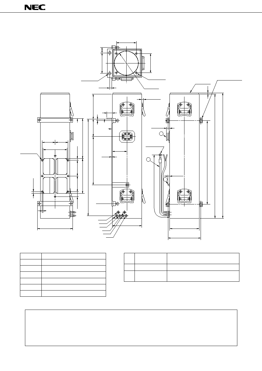
LD7215, LD7215C* and LD7215D OUTLINE (Unit in mm)
No part of this document may be copied in any form or by any means without the prior written consent of
NEC Corporation.
NEC Corporation does not assume any liability for infringement of patents, copyrights or other intellectual
property rights of third parties by or arising from use of a device described herein or any other liability arising
from use of such device. No license, either express, implied or otherwise, is granted under any patents, copy-
rights or other intellectual property rights of NEC Corporation or of others.
,
,,,
,
,,
,,
LEAD NO.
1
2
3
4
5
6
ELEMENT
(COLOR)
HEATER (≠)
(BROWN)
HEATER (+), CATHODE
(YELLOW)
ANODE
(BLUE)
COLLECTOR
(RED)
HELIC (GROUND)
(BLACK)
THERMALPROTECTION (GLAY)
LEAD CONNECTIONS
q
w
RF OUTPUT
RF INPUT
HIGH VOLTAGE
CONNECTIONS
e
CPR-137 FLANGE
(NO. 10-32 UNF 2B THREADED HOLES)
TYPE SMA FEMALE
FLYING LEADS WITH 6 TERMINALS
,
,
,
,
130
±
1
130
±
1
(6)
535
TYP.822
850 MAX.
35
140
160
±
1
83
±
1
83
±
1
BEARING
FACE
BEARING
FACE
AOR
INTAKE
15
±
1
100
±
1
35
±
1
150
±
13
0
±
1
230
±
2
630
±
20
320.8
±
3
116
±
1
178 MAX.
12
±
0.5
266
±
2
12
±
1
(2 HOLES)
6
16
±
1
(4 HOLES)
M4
(8 HOLES)
M4
155
±
1
5.5
±
1
230 MAX.
193 MAX.
No.6
No.5
No.4
No.3
No.2
No.1
195 MAX.
210
1
2
3
3
±
1
97
±
1
800
±
50
14.5
±
2
TERMINAL
20 MAX.
35 MAX.
20 MAX.
RUBBER
M10
4 SPRING LOADED
CAPTIVE SCREWS
(
)
* LD7215C is electrically connected by AMP LGH 863023 Plug.