0.1 Hz to 110 GHz
NOISE
DIODES
General Specifications:
Output
White Gaussian Noise
Operating
0∞C to +55∞C
temperature
for NC100 series
-55∞C to +125∞C
for all others
Storage temperature
-65∞C to +150∞C
Specifications subject to change without notice.
Noise Com's noise diodes are the fundamental
building blocks of all noise systems. They are
hand-picked for performance characteristics that
make them ideally suited to broadband noise
generation with flat response.
All Noise Com noise diodes deliver symmetrical
white Gaussian noise and flat output power
versus frequency. The diodes are burned-in
for 168 hours, meet MIL-STD202, and are
hermetically sealed. Noise Com noise diodes
are available in a wide variety of package styles,
and in special configurations on request.
The
NC100
and
NC200 Series
diodes are
designed for audio and RF applications. The
NC300
and
NC400 Series
diodes are designed
for microwave applications in which
a 50-ohm impedance is required.
Typical small signal impedance of the
NC300
and
NC400 Series
is 10-20 ohms when a diode
is turned on. Typically the output
level is higher at low frequencies
with low currents. Driving the
diodes with more current results in more output
at higher frequencies.
Applications:
∑
Built-in test equipment (BITE)
∑
Dither circuitry for A/D converters
3 0
www.noisecom.com
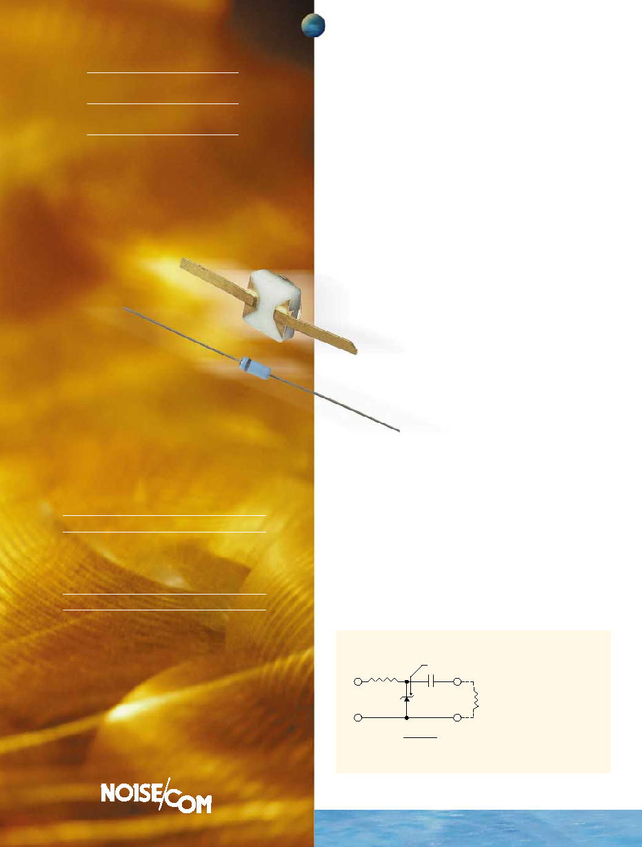
CATHODE
C
R
+
≠
15V
RF
C
1
2
R
L
(f
c
)
R
L
f
c
= low frequency cut-off
TYPICAL BIAS CIRCUIT
For NC100 Series
R = 150K
For NC200 Series
R = 15K
For NC300/400 Series
R = Adjust for performance
R
L
= Load resistor
For recommended value,
see charts on page 31
nc100/200/300/400 series

RF & MICROWAVE TYPES
MODEL FREQUENCY
OPERATING
CONDITIONS
OUTPUT
PACKAGE
RANGE Vb
(V)
Iop(mA) R
L
(
)
ENR (dB)
NC302L
10 Hz - 3 GHz
6 - 8
6
50
30 - 35
DO-35 BL CH1
NC303
10 Hz - 8 GHz
8 - 12
8
50
30 - 35
DO-35 BL CH1
NC305
10 MHz - 11 GHz
8 - 12
10
50
29 - 34
BL CH1
NC401
100 MHz - 18 GHz
8 - 12
10
50
30 - 35
C10 C50H CH2
NC403
100 MHz - 27 GHz
8 - 12
12
50
24 - 28
C50 CH3
NC404
18 GHz - 50 GHz
8 - 12
15
50
20 - 25
C50 CH3
NC405
18 GHz - 75 GHz
8 - 12
20
50
15 - 25
C50 CH3
NC406
18 GHz - 110 GHz
8 - 12
25
50
15 - 25
C50 CH3
1. For chip configuration, add suffix "C".
2. For beam lead configuration, add suffix "BL".
3. For C50H configuration, add suffix "H".
3 1
To order call 201-261-8797
NC100-400 SERIES
COMPONENTS
AUDIO & VHF TYPES
MODEL
FREQUENCY
OPERATING CONDITIONS
MINIMUM OUTPUT
PACKAGE
RANGE Vb
(V)
Iop
R
L
(
)
(µV/
Hz)
NC101
0.1 Hz - 100 kHz
7 - 10 30 - 60 µA
2200
3.0
DO-35
NC102
0.1 Hz - 500 kHz
7 - 10
30 - 60 µA
2200
3.0
DO-35
NC103
0.1 Hz - 1 MHz
7 - 10 30 - 60 µA
2200
3.0
DO-35
NC104
0.1 Hz - 3 MHz
7 - 10 30 - 60 µA
2200
3.0
DO-35
NC201
0.1 Hz - 10 MHz
7 - 10
0.2 - 0.5 mA
2200
0.1
DO-35
NC202
0.1 Hz - 25 MHz
7 - 10
0.2 - 0.5 mA
2200
0.1
DO-35
NC203
0.1 Hz - 100 MHz
7 - 10
0.2 - 0.5 mA
50
0.05
DO-35
BL Package (inches)
DO-35 Package (inches)
CH1 Chip (inches)
CH2 Chip (inches)
CH3 Chip (inches)
C10 (inches)
C50 (inches)
C50H (inches)