CF5008A1
NIPPON PRECISION CIRCUITS--1
NIPPON PRECISION CIRCUITS INC.
VCXO Module IC
OVERVIEW
The CF5008A1 is a VCXO module IC that employs a circuit structure with low parasitic capacitance effects
and a wide frequency range. Built-in components mean that few external components are required to construct
a VCXO.
FEATURES
s
Up to 30 MHz operation
s
Inverter amplifier feedback resistor built-in
s
8 mA (V
DD
= 5 V), 4 mA (V
DD
= 3 V) drive capability
s
2.7 to 5.5 V supply voltage
s
Circuit structure with low parasitic capacitance effects
∑ Direct connection to varicap diodes and crystal
s
Few external components required to form a VCXO
s
Amplitude limiting resistor Rd built-in
s
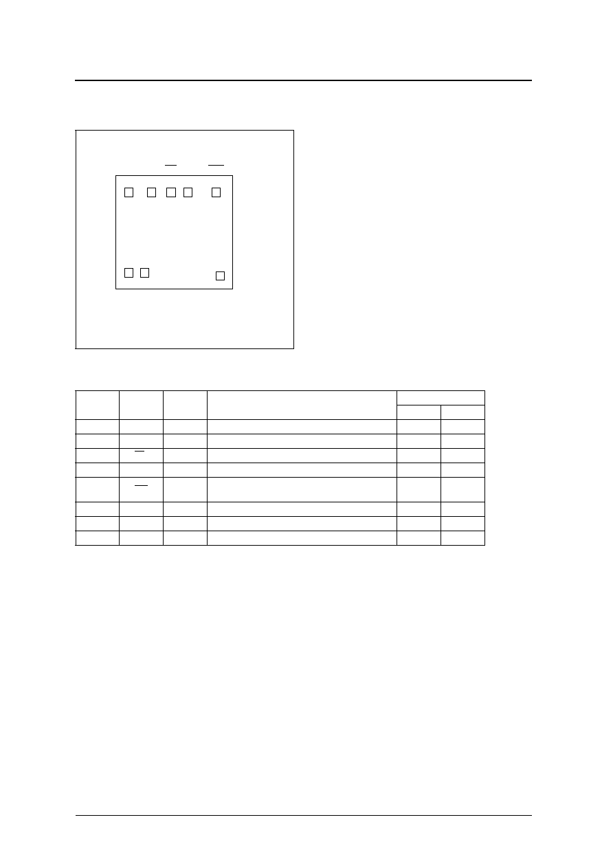
Chip form (CF5008A1)
SERIES CONFIGURATION
ORDERING INFORMATION
V ersion
Output frequency
Input level
Output duty level
S t a n d by output state
C F 5 0 0 8 A 1
f
O
C M O S
C M O S
High impedance
D e vice
P a ck ag e
C F 5 0 0 8 A 1 ≠ 2
Chip form
CF5008A1
NIPPON PRECISION CIRCUITS--5
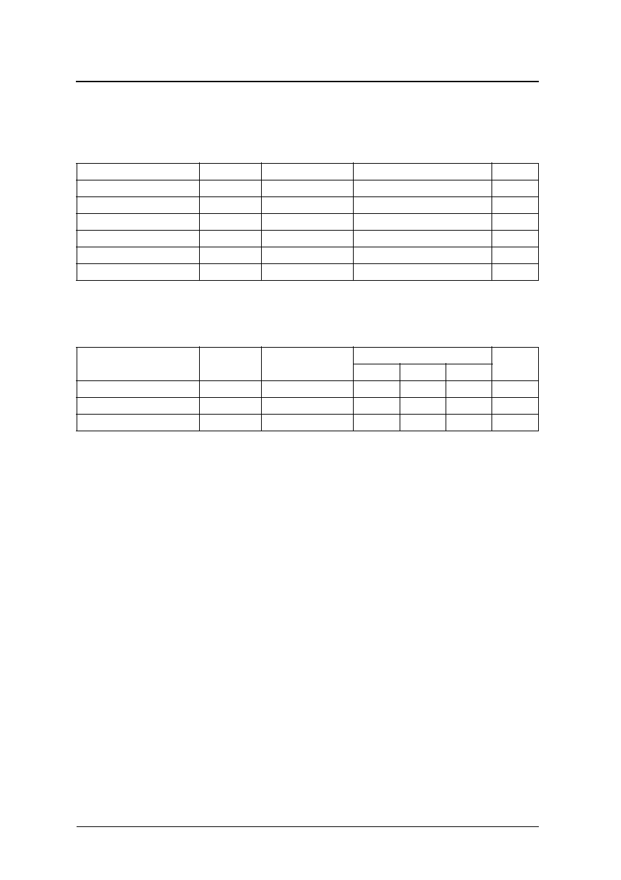
Electrical Characteristics
V
DD
= 4.5 to 5.5 V, V
SS
= 0 V, Ta =
-
20 to 80
∞
C unless otherwise noted.
Switching Characteristics
V
DD
= 2.7 to 5.5 V, V
SS
= 0 V, Ta =
-
20 to 80
∞
C unless otherwise noted.
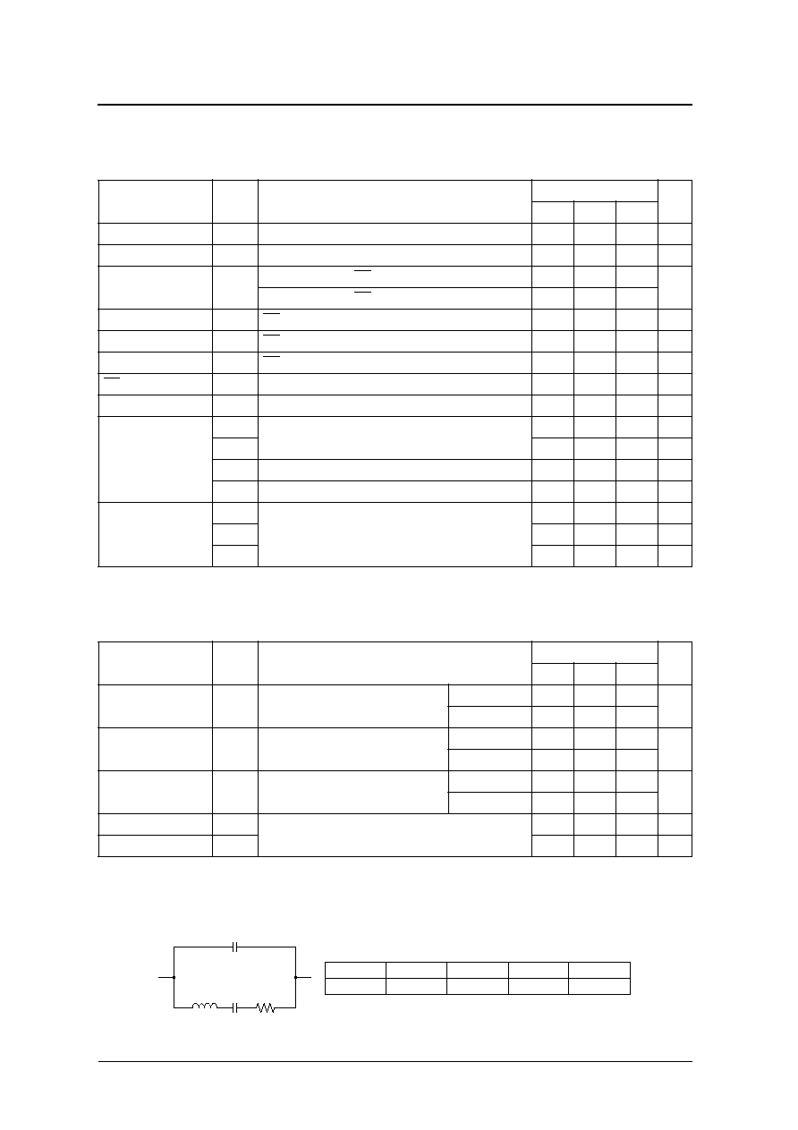
Current consumption and Output waveform with NPC's standard crystal
P arameter
S y m b o l
Condition
Rating
Unit
m i n
typ
m a x
HIGH-level output voltage
V
O H
Q: Measurement cct 1, I
O H
= 8 mA, V
D D
= 4.5 V
4.0
4.2
≠
V
L O W -level output voltage
V
O L
Q: Measurement cct 1, I
O L
= 8 mA, V
D D
= 4.5 V
≠
0.3
0.4
V
Output leakage current
I
Z
Q: Measurement cct 2, I N H = L O W , V
O H
= V
D D
≠
≠
1 0
µ A
Q: Measurement cct 2, I N H = L O W , V
O L
= V
S S
≠
≠
1 0
HIGH-level input voltage
V
IH
I N H
0.8V
D D
≠
≠
V
L O W -level input voltage
V
IL
I N H
≠
≠
0.2V
D D
V
Current consumption
I
D D
I N H = open, Measurement cct 3, load cct 1, C
L
= 15 p F, f = 30 M H z
≠
2 8
6 5
m A
I N H pull-up resistance
R
U P
Measurement cct 4
5 0
≠
1 5 0
k
F e e d b a ck resistance
R
f
Design value, determined by the internal wafer pattern
≠
1 5 0
≠
k
Built-in resistance
R
d
Design value, determined by the internal wafer pattern
≠
4 5 0
≠
R
c
≠
0
≠
R
B 1
Measurement cct 5
≠
1 0 0
≠
k
R
B 2
Measurement cct 6
≠
5 0
≠
k
Built-in capacitance
C
G
Design value, determined by the internal wafer pattern
≠
2 0
≠
p F
C
D
≠
1 0
≠
p F
C
C
≠
7 0
≠
p F
P arameter
S y m b o l
Condition
Rating
Unit
m i n
typ
m a x
Output rise time
t
r1
Measurement cct 3, load cct 1,
0.1V
D D
to 0.9V
D D
, C
L
= 15 p F
V
D D
= 2.7 to 3.6 V
≠
3
8
ns
V
D D
= 4.5 to 5.5 V
≠
2.5
6
Output fall time
t
f1
Measurement cct 3, load cct 1,
0.9V
D D
to 0.1V
D D
, C
L
= 15 p F
V
D D
= 2.7 to 3.6 V
≠
3
8
ns
V
D D
= 4.5 to 5.5 V
≠
2.5
6
Output duty cycle
1
1. Deter mined by the lot monitor.
Duty
Measurement cct 3, load cct 1, Ta = 25
∞
C ,
C
L
= 15 p F, f = 3 2 M H z
V
D D
= 3.0 V
4 2
≠
5 8
%
V
D D
= 5.0 V
4 2
≠
5 8
Output disable delay time
t
P L Z
Measurement cct 7, load cct 1, Ta = 25
∞
C , C
L
15 p F
≠
≠
1 0 0
ns
Output enable delay time
t
P Z L
≠
≠
1 0 0
ns
f (MHz)
R (
)
L (mH)
Ca (fF)
Cb (pF)
30
17.2
4.36
6.46
2.26
L
Ca
R
Cb