© 2000 National SemiconductorÆ Corporation
www.national.com
April 2000
Ge
odeTM
G
XL
V
P
r
o
ce
ssor
S
e
r
ies
L
o
w
P
o
wer
I
nte
g
rated
X
86
Solutions
GeodeTM GXLV Processor Series
Low Power Integrated x86 Solutions
General Description
The National Semiconductor
Æ
GeodeTM GXLV processor
series is a new line of integrated processors specifically
designed to power information appliances for entertain-
ment, education, and business. Serving the needs of con-
sumers and business professionals alike, it is the perfect
solution for information appliance applications such as
thin clients, interactive set top boxes, and personal inter-
net access devices.
The GXLV processor series is divided into three main cat-
egories as defined by the core operating voltage. Avail-
able with core voltages of 2.2V, 2.5V, and 2.9V, it offers
extremely low typical power consumption (1.0W to 2.5W)
leading to longer battery life and enabling small form-fac-
tor, fanless designs. Each core voltage is offered in fre-
quencies that are enabled by specific system clock and
multiplier settings. This allows the user to select the
device(s) that best fit their power and performance
requirements. This flexibility makes the GXLV processor
series ideally suited for applications where power con-
sumption and performance (speed) are equally important.
Typical power consumption is defined as an average,
measured running Microsoft's Windows at 80% Active Idle
(Suspend-on-Halt) with a display resolution of 800x600x8
bpp at 75 Hz.
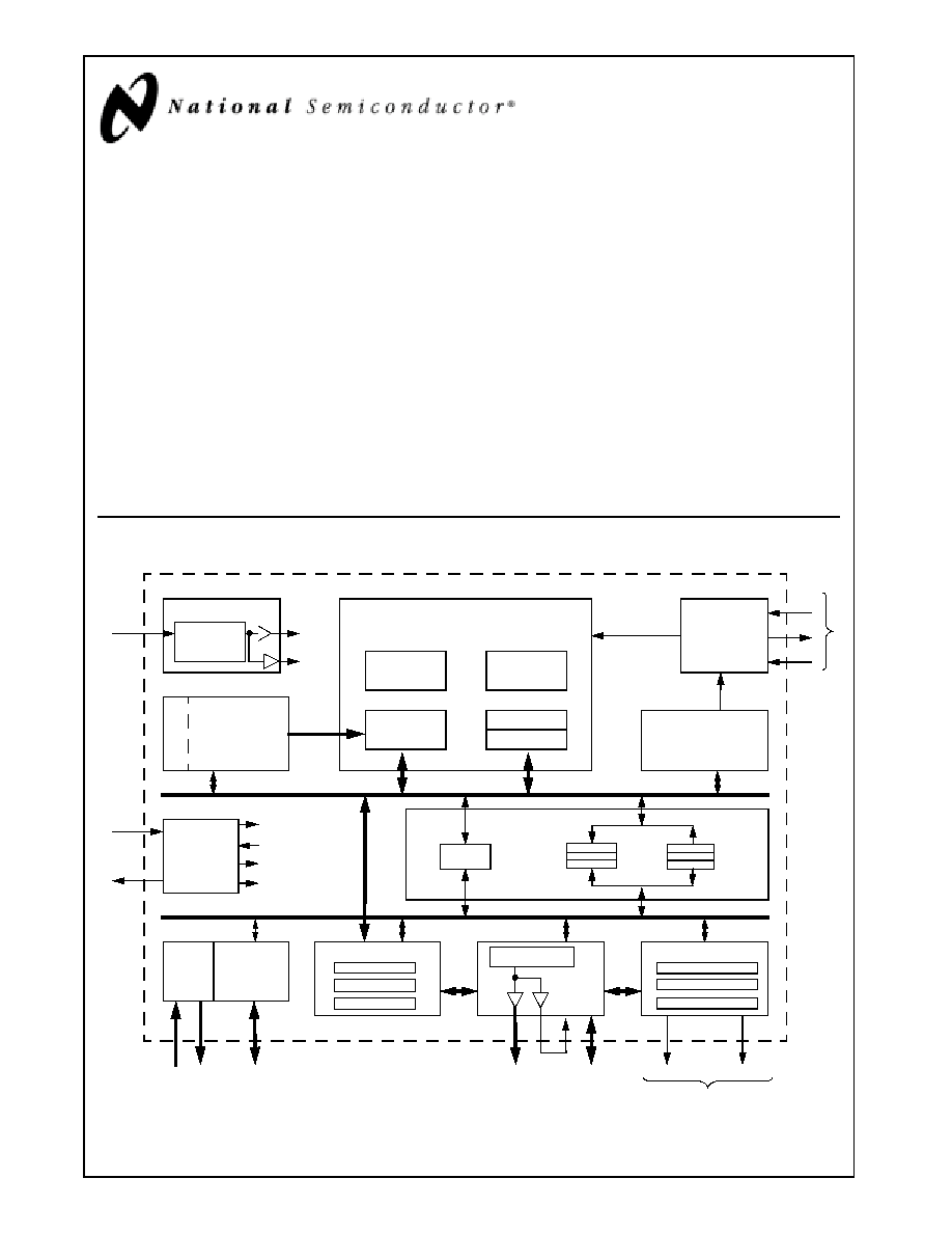
Internal Block Diagram
Interrupt
Control
Floating Point
Unit
Clock Module
SYSCLK
Core
X-Bus
X86 Compatible Core
TLB
Integer
Unit
Instruction
Fetch
MMU
Load/Store
16 KB
Unified L1
Cache
Arbiter
PCI Host
Controller
2D Accelerator
VGA
BLT Engine
ROP Unit
(128)
FP_Error
INT/NMI
X-Bus Controller
Power
Management
Control
SUSP#
SUSPA#
Core Suspend
Core Acknowledge
X-Bus Suspend
X-Bus Acknowledge
X-Bus (32)
C-Bus (64)
Write Buffers
Read Buffers
Display Controller
Compression Buffer
Palette RAM
Timing Generator
INTR
IRQ13
3
REQ/GNT
Pairs
PCI Bus
4
SDRAM
Clocks
64-bit SDRAM
RGB
YUV
Video Companion Interface
S
c
r
a
t
c
hp
ad
Arbiter
SMI#
I/O
Co
mp
an
i
o
n
Clocks
Clocks
SYSCLK
multiplied by
A
X-Bus Clk ˜ B
National Semiconductor is a registered trademark of National Semiconductor Corporation.
Geode and WebPAD are trademarks of National Semiconductor Corporation.
For a complete listing of National Semiconductor trademarks, please visit www.national.com/trademarks.

www.national.com
2
Revision 1.1
G
e
odeTM
G
XL
V
P
r
o
ce
ss
or
Se
ries
While the x86 core provides maximum compatibility with
the vast amount of internet content available, the intelli-
gent integration of several other functions, such as mem-
ory controller and graphics, offer a true system-level
multimedia solution.
The GXLV processor core is a proven x86 design that
offers competitive performance. It contains integer and
floating point execution units based on sixth-generation
technology. The integer core contains a single, five-stage
execution pipeline and offers advanced features such as
operand forwarding, branch target buffers, and extensive
write buffering. Accesses to the 16 KB write-back L1
cache are dynamically reordered to eliminate pipeline
stalls when fetching operands.
In addition to the advanced CPU features, the GXLV pro-
cessor integrates a host of functions typically imple-
mented with external components. A full function graphics
accelerator contains a Video Graphics Array (VGA) con-
troller, bitBLT engine, and a Raster Operations (ROP) unit
for complete Graphical User Interface (GUI) acceleration
under most operating systems. A display controller con-
tains additional video buffering to enable >30 fps MPEG1
playback and video overlay when used with a National
Semiconductor I/O Companion chip such as the CS5530.
Graphics and system memory accesses are supported by
a tightly coupled SDRAM controller which eliminates the
need for an external L2 cache. A PCI host controller sup-
ports up to three bus masters for additional connectivity
and multimedia capabilities.
The GXLV processor also incorporates Virtual System
Architecture
Æ
(VSATM)
technology.
VSA
technology
enables the XpressGRAPHICS and XpressAUDIO sub-
systems. Software handlers are available that provide full
compatibility for industry standard VGA and 16-bit audio
functions that are transparent at the operating system
level.
The GXLV processor is designed to be used with the
CS5530 I/O Companion, also supplied by National Semi-
conductor. Together they provide a scalable, flexible, low-
power, system-level solution well suited for a wide array of
information appliances ranging from hand-held personal
information access devices to digital set top boxes and
thin clients.
Features
General Features
Packaging:
-- 352-Terminal Ball Grid Array (BGA) or
-- 320-Pin Staggered Pin Grid Array (SPGA)
0.25-micron four layer metal CMOS process
Split rail design:
-- Available 2.2V, 2.5V, or 2.9V core
-- 3.3V I/O interface (5V tolerant)
Low typical power consumption:
-- 1.0W @ 2.2V/166 MHz
-- 2.5W @ 2.9V/266 MHz
Note:
Typical power consumption is defined as an aver-
age, measured running Windows at 80% Active
Idle (Suspend-on-Halt) with a display resolution of
800x600x8 bpp @ 75 Hz.
Speeds offered up to 266 MHz
Unified Memory Architecture:
-- Frame buffer and video memory reside in main
memory
-- Minimizes Printed Circuit Board (PCB) area require-
ments
-- Reduces system cost
Compatible with multiple Geode I/O companion
devices provided by National Semiconductor
32-Bit x86 Processor
Supports Intel's MMX instruction set extension for the
acceleration of multimedia applications
16 KB unified L1 cache
Five-stage pipelined integer unit
Integrated Floating Point Unit (FPU)
Memory Management Unit (MMU) adheres to standard
paging mechanisms and optimizes code fetch perfor-
mance:
-- Load-store reordering gives priority to memory
reads
-- Memory-read bypassing eliminates unnecessary or
redundant memory reads
Re-entrant System Management Mode (SMM)
enhanced for VSA technology
Fully Static Design
Flexible Power Management
Supports a wide variety of standards:
-- APM for Legacy power management
-- ACPI for Windows power management
≠ Direct support for all standard processor (C0-C4)
states
-- OnNOW specification compliant
Supports a wide variety of hardware and software
controlled modes:
-- Fully Active
-- Active Idle (core stopped, display active)
-- Standby (core and all integrated functions halted)
-- Sleep (core and integrated functions halted and all
external clocks stopped)
-- Suspend Modulation (automatic throttling of CPU
core)
≠ Programmable duty cycle for optimal perfor-
mance/thermal balancing
-- Several dedicated and programmable wake-up
events (via Geode I/O companion chip)

Revision 1.1
3
www.national.com
Ge
odeTM
G
XL
V
P
r
o
ce
ssor
S
e
r
ies
PCI Host Controller
Several arbitration schemes supported
Supports up to three PCI bus masters
Synchronous to CPU core
Allows external PCI master accesses to main memory
concurrent with CPU accesses to L1 cache
Virtual Systems Architecture Technology
Innovative architecture allowing OS independent (soft-
ware) virtualization of hardware functions
Provides XpressGRAPHICS subsystem:
-- High performance legacy VGA core compatibility
Note:
Uses 2D Graphics Accelerator.
Provides 16-bit XpressAUDIO subsystem:
-- 16-bit stereo FM synthesis
-- OPL3 emulation
-- Supports MPU-401 MIDI interface
-- Hardware assist provided via Geode I/O companion
chip
Additional hardware functions can be supported as
needed
2D Graphics Accelerator
Accelerates BitBLTs, line draw, text
Bresenham vector engine
Supports all 256 ROPs
Supports transparent BLTs and page flipping for
Microsoft's DirectDraw
Runs at core clock frequency
Full VGA and VESA mode support
Special "driver level" instructions utilize internal
scratchpad for enhanced performance
Display Controller
Display Compression Technology (DCT) architecture
greatly reduces memory bandwidth consumption of
display refresh
Supports a separate video buffer and data path to
enable video acceleration in Geode I/O companion
devices
Internal palette RAM for gamma correction
Direct interface to Geode I/O companion devices for
CRT and TFT flat panel support eliminates the need for
an external RAMDAC
Hardware cursor
Supports up to 1280x1024x8 bpp and
1024x768x16 bpp
XpressRAM Subsystem
SDRAM interface tightly coupled to CPU core and
graphics subsystem for maximum efficiency
64-Bit wide memory bus
Support for:
-- Two 168-pin unbuffered DIMMs
-- Up to 16 simultaneously open banks
-- 16-byte reads (burst length of two)
-- Up to 256 MB total memory supported
Diverse Operating System Support
Microsoft's Windows 2000, 9X, NT, and CE
Sun Microsystems' Java
WindRiver Systems' VxWorks
QNX Software Systems' QNX
Linux

www.national.com
4
Revision 1.1
Table of Contents
G
e
odeTM
G
XL
V
P
r
o
ce
ss
or
Se
ries
1.0
Architecture Overview . . . . . . . . . . . . . . . . . . . . . . . . . . . . . . . . . . . . . . . . . . . . . 10
1.1
INTEGER UNIT . . . . . . . . . . . . . . . . . . . . . . . . . . . . . . . . . . . . . . . . . . . . . . . . . . . . . . . . . . 11
1.2
FLOATING POINT UNIT . . . . . . . . . . . . . . . . . . . . . . . . . . . . . . . . . . . . . . . . . . . . . . . . . . . 11
1.3
WRITE-BACK CACHE UNIT . . . . . . . . . . . . . . . . . . . . . . . . . . . . . . . . . . . . . . . . . . . . . . . . 11
1.4
MEMORY MANAGEMENT UNIT . . . . . . . . . . . . . . . . . . . . . . . . . . . . . . . . . . . . . . . . . . . . . 11
1.5
INTERNAL BUS INTERFACE UNIT . . . . . . . . . . . . . . . . . . . . . . . . . . . . . . . . . . . . . . . . . . . 11
1.6
INTEGRATED FUNCTIONS . . . . . . . . . . . . . . . . . . . . . . . . . . . . . . . . . . . . . . . . . . . . . . . . 12
1.6.1
Graphics Accelerator . . . . . . . . . . . . . . . . . . . . . . . . . . . . . . . . . . . . . . . . . . . . . . . 12
1.6.2
Display Controller . . . . . . . . . . . . . . . . . . . . . . . . . . . . . . . . . . . . . . . . . . . . . . . . . . 12
1.6.3
XpressRAM Memory Subsystem . . . . . . . . . . . . . . . . . . . . . . . . . . . . . . . . . . . . . . 12
1.6.4
PCI Controller . . . . . . . . . . . . . . . . . . . . . . . . . . . . . . . . . . . . . . . . . . . . . . . . . . . . . 12
1.7
GEODE GXLV/CS5530 SYSTEM DESIGNS . . . . . . . . . . . . . . . . . . . . . . . . . . . . . . . . . . . . 13
1.7.1
Reference Designs . . . . . . . . . . . . . . . . . . . . . . . . . . . . . . . . . . . . . . . . . . . . . . . . . 16
2.0
Signal Definitions . . . . . . . . . . . . . . . . . . . . . . . . . . . . . . . . . . . . . . . . . . . . . . . . . 19
2.1
PIN ASSIGNMENTS . . . . . . . . . . . . . . . . . . . . . . . . . . . . . . . . . . . . . . . . . . . . . . . . . . . . . . 20
2.2
SIGNAL DESCRIPTIONS . . . . . . . . . . . . . . . . . . . . . . . . . . . . . . . . . . . . . . . . . . . . . . . . . . 31
2.2.1
System Interface Signals . . . . . . . . . . . . . . . . . . . . . . . . . . . . . . . . . . . . . . . . . . . . 31
2.2.2
PCI Interface Signals . . . . . . . . . . . . . . . . . . . . . . . . . . . . . . . . . . . . . . . . . . . . . . . 33
2.2.3
Memory Controller Interface Signals . . . . . . . . . . . . . . . . . . . . . . . . . . . . . . . . . . . 36
2.2.4
Video Interface Signals . . . . . . . . . . . . . . . . . . . . . . . . . . . . . . . . . . . . . . . . . . . . . 37
2.2.5
Power, Ground, and No Connect Signals . . . . . . . . . . . . . . . . . . . . . . . . . . . . . . . . 39
2.2.6
Internal Test and Measurement Signals . . . . . . . . . . . . . . . . . . . . . . . . . . . . . . . . . 39
3.0
Processor Programming . . . . . . . . . . . . . . . . . . . . . . . . . . . . . . . . . . . . . . . . . . . 41
3.1
CORE PROCESSOR INITIALIZATION . . . . . . . . . . . . . . . . . . . . . . . . . . . . . . . . . . . . . . . . 41
3.2
INSTRUCTION SET OVERVIEW . . . . . . . . . . . . . . . . . . . . . . . . . . . . . . . . . . . . . . . . . . . . . 42
3.2.1
Lock Prefix . . . . . . . . . . . . . . . . . . . . . . . . . . . . . . . . . . . . . . . . . . . . . . . . . . . . . . . 42
3.3
REGISTER SETS . . . . . . . . . . . . . . . . . . . . . . . . . . . . . . . . . . . . . . . . . . . . . . . . . . . . . . . . . 43
3.3.1
Application Register Set . . . . . . . . . . . . . . . . . . . . . . . . . . . . . . . . . . . . . . . . . . . . . 43
3.3.1.1
General Purpose Registers . . . . . . . . . . . . . . . . . . . . . . . . . . . . . . . . . . . . . . . . . . 43
3.3.1.2
Segment Registers . . . . . . . . . . . . . . . . . . . . . . . . . . . . . . . . . . . . . . . . . . . . . . . . 45
3.3.1.3
Instruction Pointer Register . . . . . . . . . . . . . . . . . . . . . . . . . . . . . . . . . . . . . . . . . . 45
3.3.1.4
EFLAGS Register . . . . . . . . . . . . . . . . . . . . . . . . . . . . . . . . . . . . . . . . . . . . . . . . . 46
3.3.2
System Register Set . . . . . . . . . . . . . . . . . . . . . . . . . . . . . . . . . . . . . . . . . . . . . . . 47
3.3.2.1
Control Registers . . . . . . . . . . . . . . . . . . . . . . . . . . . . . . . . . . . . . . . . . . . . . . . . . . 48
3.3.2.2
Configuration Registers . . . . . . . . . . . . . . . . . . . . . . . . . . . . . . . . . . . . . . . . . . . . . 50
3.3.2.3
Debug Registers . . . . . . . . . . . . . . . . . . . . . . . . . . . . . . . . . . . . . . . . . . . . . . . . . . 55
3.3.2.4
TLB Test Registers . . . . . . . . . . . . . . . . . . . . . . . . . . . . . . . . . . . . . . . . . . . . . . . . 57
3.3.2.5
Cache Test Registers . . . . . . . . . . . . . . . . . . . . . . . . . . . . . . . . . . . . . . . . . . . . . . 59
3.3.3
Model Specific Register Set . . . . . . . . . . . . . . . . . . . . . . . . . . . . . . . . . . . . . . . . . . 62
3.3.4
Time Stamp Counter . . . . . . . . . . . . . . . . . . . . . . . . . . . . . . . . . . . . . . . . . . . . . . . 62
3.4
ADDRESS SPACES . . . . . . . . . . . . . . . . . . . . . . . . . . . . . . . . . . . . . . . . . . . . . . . . . . . . . . . 63
3.4.1
I/O Address Space . . . . . . . . . . . . . . . . . . . . . . . . . . . . . . . . . . . . . . . . . . . . . . . . . 63
3.4.2
Memory Address Space . . . . . . . . . . . . . . . . . . . . . . . . . . . . . . . . . . . . . . . . . . . . . 64

Revision 1.1
5
www.national.com
Table of Contents (
Continued
)
Ge
odeTM
G
XL
V
P
r
o
ce
ssor
S
e
r
ies
3.5
OFFSET, SEGMENT, AND PAGING MECHANISMS . . . . . . . . . . . . . . . . . . . . . . . . . . . . . 64
3.5.1
Offset Mechanism . . . . . . . . . . . . . . . . . . . . . . . . . . . . . . . . . . . . . . . . . . . . . . . . . 64
3.5.2
Segment Mechanisms . . . . . . . . . . . . . . . . . . . . . . . . . . . . . . . . . . . . . . . . . . . . . . 66
3.5.2.1
Real Mode Segment Mechanism . . . . . . . . . . . . . . . . . . . . . . . . . . . . . . . . . . . . . 66
3.5.2.2
Virtual 8086 Mode Segment Mechanism . . . . . . . . . . . . . . . . . . . . . . . . . . . . . . . . 66
3.5.2.3
Segment Mechanism in Protected Mode . . . . . . . . . . . . . . . . . . . . . . . . . . . . . . . . 67
3.5.2.4
Segment Selectors . . . . . . . . . . . . . . . . . . . . . . . . . . . . . . . . . . . . . . . . . . . . . . . . 67
3.5.3
Descriptors . . . . . . . . . . . . . . . . . . . . . . . . . . . . . . . . . . . . . . . . . . . . . . . . . . . . . . . 70
3.5.3.1
Global and Local Descriptor Table Registers . . . . . . . . . . . . . . . . . . . . . . . . . . . . . 70
3.5.3.2
Segment Descriptors . . . . . . . . . . . . . . . . . . . . . . . . . . . . . . . . . . . . . . . . . . . . . . . 70
3.5.3.3
Task, Gate, Interrupt, and Application and System Descriptors . . . . . . . . . . . . . . 71
3.5.4
Paging Mechanism . . . . . . . . . . . . . . . . . . . . . . . . . . . . . . . . . . . . . . . . . . . . . . . . . 77
3.6
INTERRUPTS AND EXCEPTIONS . . . . . . . . . . . . . . . . . . . . . . . . . . . . . . . . . . . . . . . . . . . 79
3.6.1
Interrupts . . . . . . . . . . . . . . . . . . . . . . . . . . . . . . . . . . . . . . . . . . . . . . . . . . . . . . . . 79
3.6.2
Exceptions . . . . . . . . . . . . . . . . . . . . . . . . . . . . . . . . . . . . . . . . . . . . . . . . . . . . . . . 79
3.6.3
Interrupt Vectors . . . . . . . . . . . . . . . . . . . . . . . . . . . . . . . . . . . . . . . . . . . . . . . . . . . 80
3.6.3.1
Interrupt Vector Assignments . . . . . . . . . . . . . . . . . . . . . . . . . . . . . . . . . . . . . . . . . 80
3.6.3.2
Interrupt Descriptor Table . . . . . . . . . . . . . . . . . . . . . . . . . . . . . . . . . . . . . . . . . . . 80
3.6.4
Interrupt and Exception Priorities . . . . . . . . . . . . . . . . . . . . . . . . . . . . . . . . . . . . . . 81
3.6.5
Exceptions in Real Mode . . . . . . . . . . . . . . . . . . . . . . . . . . . . . . . . . . . . . . . . . . . . 82
3.6.6
Error Codes . . . . . . . . . . . . . . . . . . . . . . . . . . . . . . . . . . . . . . . . . . . . . . . . . . . . . . 82
3.7
SYSTEM MANAGEMENT MODE . . . . . . . . . . . . . . . . . . . . . . . . . . . . . . . . . . . . . . . . . . . . 83
3.7.1
SMM Operation . . . . . . . . . . . . . . . . . . . . . . . . . . . . . . . . . . . . . . . . . . . . . . . . . . . 84
3.7.2
SMI# Pin . . . . . . . . . . . . . . . . . . . . . . . . . . . . . . . . . . . . . . . . . . . . . . . . . . . . . . . . . 85
3.7.3
SMM Configuration Registers . . . . . . . . . . . . . . . . . . . . . . . . . . . . . . . . . . . . . . . . 85
3.7.4
SMM Memory Space Header . . . . . . . . . . . . . . . . . . . . . . . . . . . . . . . . . . . . . . . . . 85
3.7.5
SMM Instructions . . . . . . . . . . . . . . . . . . . . . . . . . . . . . . . . . . . . . . . . . . . . . . . . . . 87
3.7.6
SMM Memory Space . . . . . . . . . . . . . . . . . . . . . . . . . . . . . . . . . . . . . . . . . . . . . . . 88
3.7.7
SMI Generation for Virtual VGA . . . . . . . . . . . . . . . . . . . . . . . . . . . . . . . . . . . . . . . 88
3.7.8
SMM Service Routine Execution . . . . . . . . . . . . . . . . . . . . . . . . . . . . . . . . . . . . . . 88
3.7.8.1
SMI Nesting . . . . . . . . . . . . . . . . . . . . . . . . . . . . . . . . . . . . . . . . . . . . . . . . . . . . . . 88
3.7.8.2
CPU States Related to SMM and Suspend Mode . . . . . . . . . . . . . . . . . . . . . . . . . 90
3.8
HALT AND SHUTDOWN . . . . . . . . . . . . . . . . . . . . . . . . . . . . . . . . . . . . . . . . . . . . . . . . . . . 91
3.9
PROTECTION . . . . . . . . . . . . . . . . . . . . . . . . . . . . . . . . . . . . . . . . . . . . . . . . . . . . . . . . . . . 91
3.9.1
Privilege Levels . . . . . . . . . . . . . . . . . . . . . . . . . . . . . . . . . . . . . . . . . . . . . . . . . . . 91
3.9.2
I/O Privilege Levels . . . . . . . . . . . . . . . . . . . . . . . . . . . . . . . . . . . . . . . . . . . . . . . . 91
3.9.3
Privilege Level Transfers . . . . . . . . . . . . . . . . . . . . . . . . . . . . . . . . . . . . . . . . . . . . 92
3.9.3.1
Gates . . . . . . . . . . . . . . . . . . . . . . . . . . . . . . . . . . . . . . . . . . . . . . . . . . . . . . . . . . . 93
3.9.4
Initialization and Transition to Protected Mode . . . . . . . . . . . . . . . . . . . . . . . . . . . . 93
3.10
VIRTUAL 8086 MODE . . . . . . . . . . . . . . . . . . . . . . . . . . . . . . . . . . . . . . . . . . . . . . . . . . . . . 93
3.10.1
Memory Addressing . . . . . . . . . . . . . . . . . . . . . . . . . . . . . . . . . . . . . . . . . . . . . . . . 93
3.10.2
Protection . . . . . . . . . . . . . . . . . . . . . . . . . . . . . . . . . . . . . . . . . . . . . . . . . . . . . . . . 93
3.10.3
Interrupt Handling . . . . . . . . . . . . . . . . . . . . . . . . . . . . . . . . . . . . . . . . . . . . . . . . . . 93
3.10.4
Entering and Leaving Virtual 8086 Mode . . . . . . . . . . . . . . . . . . . . . . . . . . . . . . . . 93
3.11
FLOATING POINT UNIT OPERATIONS . . . . . . . . . . . . . . . . . . . . . . . . . . . . . . . . . . . . . . . 94
3.11.1
FPU Register Set . . . . . . . . . . . . . . . . . . . . . . . . . . . . . . . . . . . . . . . . . . . . . . . . . . 94
3.11.2
FPU Tag Word Register . . . . . . . . . . . . . . . . . . . . . . . . . . . . . . . . . . . . . . . . . . . . . 94
3.11.3
FPU Status Register . . . . . . . . . . . . . . . . . . . . . . . . . . . . . . . . . . . . . . . . . . . . . . . 94
3.11.4
FPU Mode Control Register . . . . . . . . . . . . . . . . . . . . . . . . . . . . . . . . . . . . . . . . . . 94