TL F 10492
DP83932C-202533
MHz
SONIC
Systems-Oriented
Network
Interface
Controller
July 1995
DP83932C-20 25 33 MHz SONIC
TM
Systems-Oriented Network Interface Controller
General Description
The SONIC (Systems-Oriented Network Interface Control-
ler) is a second-generation Ethernet Controller designed to
meet the demands of today's high-speed 32- and 16-bit sys-
tems Its system interface operates with a high speed DMA
that typically consumes less than 3% of the bus bandwidth
(25 MHz bus clock) Selectable bus modes provide both big
and little endian byte ordering and a clean interface to stan-
dard microprocessors The linked-list buffer management
system of SONIC offers maximum flexibility in a variety of
environments from PC-oriented adapters to high-speed
motherboard designs Furthermore the SONIC integrates a
fully-compatible IEEE 802 3 Encoder Decoder (ENDEC) al-
lowing for a simple 2-chip solution for Ethernet when the
SONIC is paired with the DP8392 Coaxial Transceiver Inter-
face or a 10BASE-T transceiver
For increased performance
the SONIC implements a
unique buffer management scheme to efficiently process
receive and transmit packets in system memory No inter-
mediate packet copy is necessary The receive buffer man-
agement uses three areas in memory for (1) allocating addi-
tional resources (2) indicating status information and (3)
buffering packet data During reception the SONIC stores
packets in the buffer area then indicates receive status and
control information in the descriptor area The system allo-
cates more memory resources to the SONIC by adding de-
scriptors to the memory resource area The transmit buffer
management uses two areas in memory one for indicating
status and control information and the other for fetching
packet data The system can create a transmit queue allow-
ing multiple packets to be transmitted from a single transmit
command The packet data can reside on any arbitrary byte
boundary and can exist in several non-contiguous locations
Features
Y
32-bit non-multiplexed address and data bus
Y
High-speed interruptible DMA
Y
Linked-list buffer management maximizes flexibility
Y
Two independent 32-byte transmit and receive FIFOs
Y
Bus compatibility for all standard microprocessors
Y
Supports big and little endian formats
Y
Integrated IEEE 802 3 ENDEC
Y
Complete address filtering for up to 16 physical and or
multicast addresses
Y
32-bit general-purpose timer
Y
Full-duplex loopback diagnostics
Y
Fabricated in low-power CMOS
Y
132 PQFP package
Y
Full network management facilities support the 802 3
layer management standard
Y
Integrated support for bridge and repeater applications
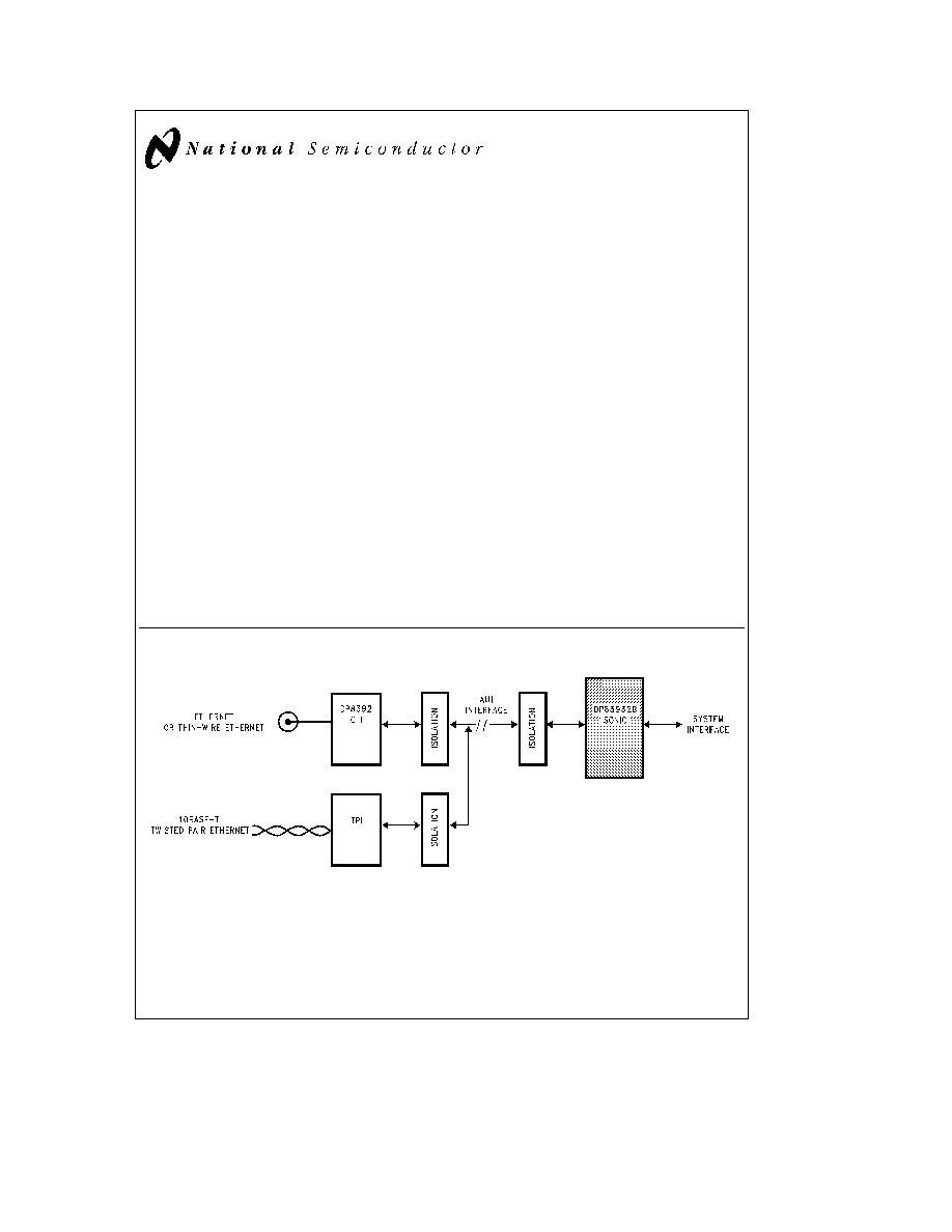
System Diagram
TL F 10492 ≠ 2
TRI-STATE
is a registered trademark of National Semiconductor Corporation
SONIC
TM
is a trademark of National Semiconductor Corporation
C1995 National Semiconductor Corporation
RRD-B30M105 Printed in U S A

Table of Contents
1 0 FUNCTIONAL DESCRIPTION
1 1 IEEE 802 3 ENDEC Unit
1 1 1 ENDEC Operation
1 1 2 Selecting an External ENDEC
1 2 MAC Unit
1 2 1 MAC Receive Section
1 2 2 MAC Transmit Section
1 3 Data Width and Byte Ordering
1 4 FIFO and Control Logic
1 4 1 Receive FIFO
1 4 2 Transmit FIFO
1 5 Status and Configuration Registers
1 6 Bus Interface
1 7 Loopback and Diagnostics
1 7 1 Loopback Procedure
1 8 Network Management Functions
2 0 TRANSMIT RECEIVE IEEE 802 3
FRAME FORMAT
2 1 Preamble and Start Of Frame Delimiter (SFD)
2 2 Destination Address
2 3 Source Address
2 4 Length Type Field
2 5 Data Field
2 6 FCS Field
2 7 MAC (Media Access Control) Conformance
3 0 BUFFER MANAGEMENT
3 1 Buffer Management Overview
3 2 Descriptor Areas
3 2 1 Naming Convention for Descriptors
3 2 2 Abbreviations
3 2 3 Buffer Management Base Addresses
3 3 Descriptor Data Alignment
3 4 Receive Buffer Management
3 4 1 Receive Resource Area (RRA)
3 4 2 Receive Buffer Area (RBA)
3 4 3 Receive Descriptor Area (RDA)
3 4 4 Receive Buffer Management Initialization
3 4 5 Beginning of Reception
3 4 6 End of Packet Processing
3 4 7 Overflow Conditions
3 5 Transmit Buffer Management
3 5 1 Transmit Descriptor Area (TDA)
3 5 2 Transmit Buffer Area (TBA)
3 5 3 Preparing to Transmit
3 5 4 Dynamically Adding TDA Descriptors
4 0 SONIC REGISTERS
4 1 The CAM Unit
4 1 1 The Load CAM Command
4 2 Status Control Registers
4 3 Register Description
4 3 1 Command Register
4 3 2 Data Configuration Register
4 3 3 Receive Control Register
4 3 4 Transmit Control Register
4 3 5 Interrupt Mask Register
4 3 6 Interrupt Status Register
4 3 7 Data Configuration Register 2
4 3 8 Transmit Registers
4 3 9 Receive Registers
4 3 10 CAM Registers
4 3 11 Tally Counters
4 3 12 General Purpose Timer
4 3 13 Silicon Revision Register
5 0 BUS INTERFACE
5 1 Pin Configurations
5 2 Pin Description
5 3 System Configuration
5 4 Bus Operations
5 4 1 Acquiring the Bus
5 4 2 Block Transfers
5 4 3 Bus Status
5 4 4 Bus Mode Compatibility
5 4 5 Master Mode Bus Cycles
5 4 6 Bus Exceptions (Bus Retry)
5 4 7 Slave Mode Bus Cycle
5 4 8 On-Chip Memory Arbiter
5 4 9 Chip Reset
6 0 NETWORK INTERFACING
6 1 Manchester Encoder and Differential Driver
6 1 1 Manchester Decoder
6 1 2 Collision Translator
6 1 3 Oscillator Inputs
6 1 4 Power Supply Considerations
7 0 AC AND DC SPECIFICATIONS
8 0 AC TIMING TEST CONDITIONS
2
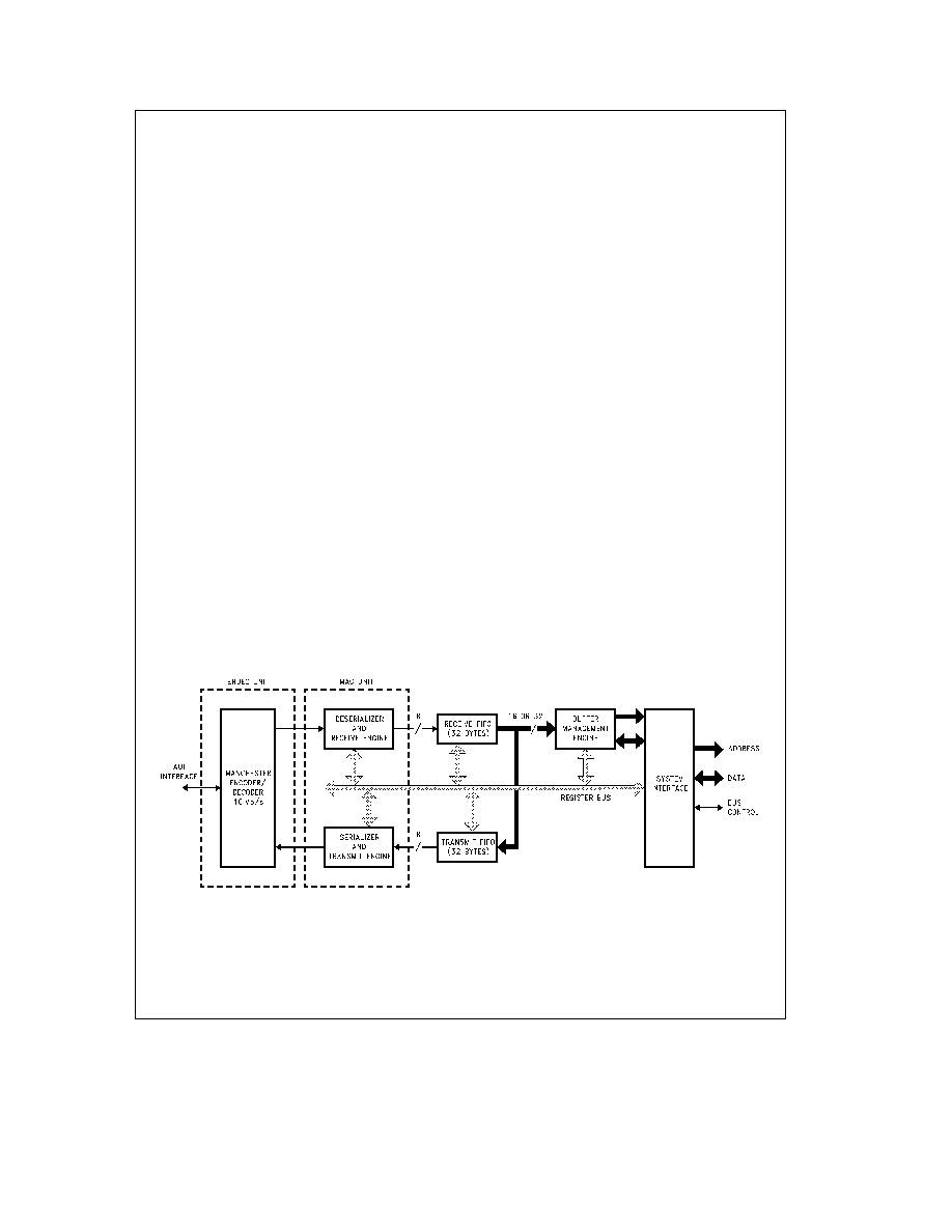
1 0 Functional Description
The SONIC
(Figure 1-1 ) consists of an encoder decoder
(ENDEC) unit media access control (MAC) unit separate
receive and transmit FIFOs a system buffer management
engine and a user programmable system bus interface unit
on a single chip SONIC is highly pipelined providing maxi-
mum system level performance This section provides a
functional overview of SONIC
1 1 IEEE 802 3 ENDEC UNIT
The ENDEC (Encoder Decoder) unit is the interface be-
tween the Ethernet transceiver and the MAC unit It pro-
vides the Manchester data encoding and decoding func-
tions for IEEE 802 3 Ethernet Thin-Ethernet type local area
networks The ENDEC operations of SONIC are identical to
the DP83910A CMOS Serial Network Interface device Dur-
ing transmission the ENDEC unit combines non-return-zero
(NRZ) data from the MAC section and clock pulses into
Manchester data and sends the converted data differentially
to the transceiver Conversely during reception an analog
PLL decodes the Manchester data to NRZ format and re-
ceive clock The ENDEC unit is a functionally complete
Manchester encoder decoder incorporating a balanced
driver and receiver on-board crystal oscillator collision sig-
nal translator and a diagnostic loopback The features in-
clude
Compatible with Ethernet I and II IEEE 802 3 10base5
and 10base2
10Mb s Manchester encoding decoding with receive
clock recovery
Requires no precision components
Loopback capability for diagnostics
Externally selectable half or full step modes of operation
at transmit output
Squelch circuitry at the receive and collision inputs reject
noise
Connects to the transceiver (AUI) cable via external
pulse transformer
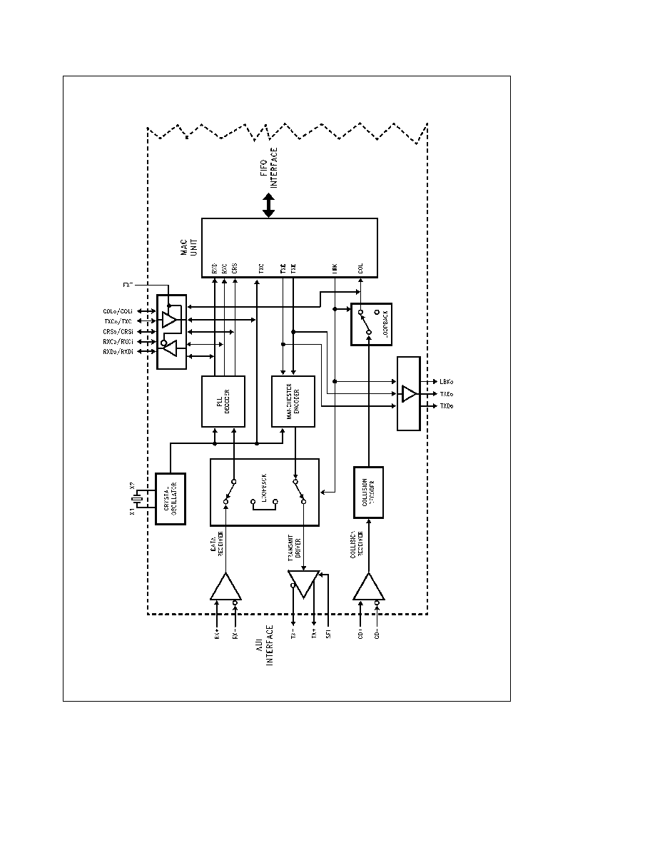
1 1 1 ENDEC Operation
The primary function of the ENDEC unit
(Figure 1-2 ) is to
perform the encoding and decoding necessary for compati-
bility between the differential pair Manchester encoded data
of the transceiver and the Non-Return-to-Zero (NRZ) serial
data of the MAC unit data line In addition to encoding and
decoding the data stream the ENDEC also supplies all the
necessary special signals (e g
collision detect
carrier
sense and clocks) to the MAC unit The signals provided to
the MAC unit from the on-chip ENDEC are also provided as
outputs to the user
Manchester Encoder and Differential Output Driver
During transmission to the network the ENDEC unit trans-
lates the NRZ serial data from the MAC unit into differential
pair Manchester encoded data on the Coaxial Transceiver
Interface (e g National's DP8392) transmit pair To perform
this operation the NRZ bit stream from the MAC unit is
passed through the Manchester encoder block of the
ENDEC unit Once the bit stream is encoded it is transmit-
ted out differentially to the transmit differential pair through
the transmit driver
Manchester Decoder
During reception from the network
the differential receive data from the transceiver (e g the
DP8392) is converted from Manchester encoded data into
NRZ serial data and a receive clock which are sent to the
receive data and clock inputs of the MAC unit To perform
this operation the signal once received by the differential
receiver is passed to the phase locked loop (PLL) decoder
block The PLL decodes the data and generates a data re-
ceive clock and a NRZ serial data stream to the MAC unit
Special Signals
In addition to performing the Manchester
encoding and decoding function the ENDEC unit provides
control and clocking signals to the MAC unit The ENDEC
sends a carrier sense (CRS) signal that indicates to the
MAC unit that data is present from the network on the
ENDEC's receive differential pair The MAC unit is also pro-
vided with a collision detection signal (COL) that informs the
MAC unit that a collision is taking place somewhere on
TL F 10492 ≠ 1
FIGURE 1-1 SONIC Block Diagram
3
1 0 Functional Description
(Continued)
TLF10492
≠
3
FIGURE
1-2
Block
Diagram
of
Ethernet
ENDEC
4
1 0 Functional Description
(Continued)
the network The ENDEC section detects this when its colli-
sion receiver detects a 10 MHz signal on the differential
collision input pair The ENDEC also provides both the re-
ceive and transmit clocks to the MAC unit The transmit
clock is one half of the oscillator input The receive clock is
extracted from the input data by the PLL
Oscillator
The oscillator generates the 10 MHz transmit
clock signal for network timing The oscillator is controlled
by a parallel resonant crystal or by an external clock (see
Section 6 1 3) The 20 MHz output of the oscillator is divided
by 2 to generate the 10 MHz transmit clock (TXC) for the
MAC section The oscillator provides an internal clock signal
for the encoding and decoding circuits
Loopback Functions
The SONIC provides three loopback
modes These modes allow loopback testing at the MAC
ENDEC and external transceiver level (see Section 1 7 for
details) It is important to note that when the SONIC is trans-
mitting the transmitted packet will always be looped back
by the external transceiver The SONIC takes advantage of
this to monitor the transmitted packet See the explanation
of the Receive State Machine in Section 1 2 1 for more in-
formation about monitoring transmitted packets
1 1 2 Selecting An External ENDEC
An option is provided on SONIC to disable the on-chip
ENDEC unit and use an external ENDEC The internal IEEE
802 3 ENDEC can be bypassed by connecting the EXT pin
to V
CC
(EXT
e
1) In this mode the MAC signals are redirect-
ed allowing an external ENDEC to be used See Section 5 2
for the alternate pin definitions
1 2 MAC UNIT
The MAC (Media Access Control) unit performs the media
access control functions for transmitting and receiving pack-
ets over Ethernet During transmission the MAC unit frames
information from the transmit FIFO and supplies serialized
data to the ENDEC unit During reception the incoming in-
formation from the ENDEC unit is deserialized the frame
checked for valid reception and the data is transferred to
the receive FIFO Control and status registers on the SONIC
govern the operation of the MAC unit
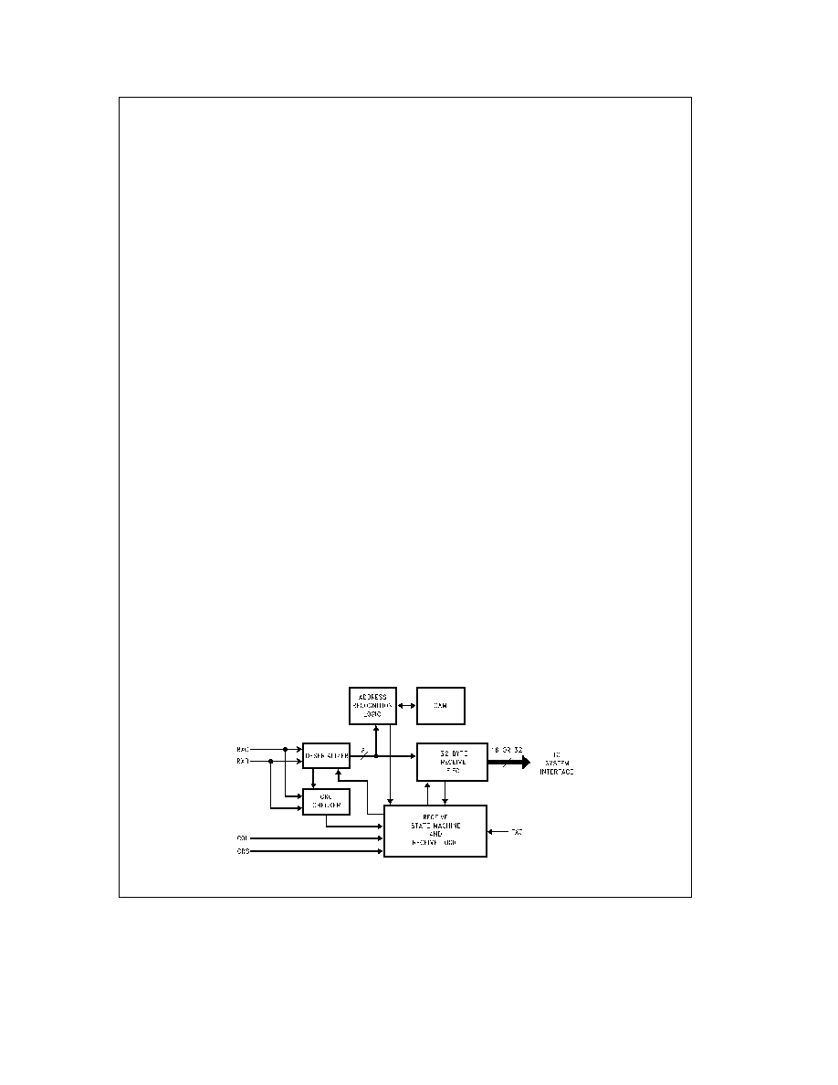
1 2 1 MAC Receive Section
The receive section
(Figure 1-3 ) controls the MAC receive
operations during reception loopback and transmission
During reception the deserializer goes active after detecting
the one byte SFD (Start of Frame Delimiter) pattern (Section
2 1) consisting of a ``10101011'' sequence It then frames
the incoming bits into octet boundaries and transfers the
data to the 32-byte receive FIFO Concurrently the address
comparator compares the Destination Address Field to the
addresses stored in the chip's CAM address registers (Con-
tent Addressable Memory cells) If a match occurs the de-
serializer passes the remainder of the packet to the receive
FIFO The packet is decapsulated when the carrier sense
input pin (CRS) goes inactive At the end of reception the
receive section checks the following
Frame alignment errors
CRC errors
Length errors (runt packets)
The appropriate status is indicated in the Receive Control
register (Section 4 3 3) In loopback operations the receive
section operates the same as during normal reception
During transmission the receive section remains active to
allow monitoring of the self-received packet The CRC
checker operates as normal and the Source Address field
is compared with the CAM address entries Status of the
CRC check and the source address comparison is indicated
by the PMB bit in the Transmit Control register (Section
4 3 4) No data is written to the receive FIFO during transmit
operations
The receive section consists of the following blocks detailed
below
Receive State Machine (RSM)
The RSM insures the prop-
er sequencing for normal reception and self-reception dur-
ing transmission When the network is inactive the RSM
remains in an idle state continually monitoring for network
activity If the network becomes active the RSM allows the
deserializer to write data into the receive FIFO During this
state the following conditions may prevent the complete
reception of the packet
FIFO Overrun
The receive FIFO has been completely
filled before the SONIC could buffer the data to memory
CAM Address Mismatch
The packet is rejected be-
cause of a mismatch between the destination address of
the packet and the address in the CAM
Memory Resource Error
There are no more resources
(buffers) available for buffering the incoming packets
Collision or Other Error
A collision occured on the net-
work or some other error such as a CRC error occurred
(this is true if the SONIC has been told to reject packets
on a collision or reject packets with errors)
If these conditions do not occur the RSM processes the
packet indicating the appropriate status in the Receive Con-
trol register
TL F 10492 ≠ 4
FIGURE 1-3 MAC Receiver
5