 | ÐлекÑÑоннÑй компоненÑ: LM1819 | СкаÑаÑÑ:  PDF PDF  ZIP ZIP |
Äîêóìåíòàöèÿ è îïèñàíèÿ www.docs.chipfind.ru
TL H 5263
LM1819
Air-Core
Meter
Driver
February 1995
LM1819 Air-Core Meter Driver
General Description
The LM1819 is a function generator driver for air-core
(moving-magnet) meter movements A Norton amplifier and
an NPN transistor are included on chip for signal condition-
ing as required Driver outputs are self-centering and devel-
op
g
4 5V swing at 20 mA Better than 2% linearity is guar-
anteed over a full 305-degree operating range
Features
Y
Self-centering 20 mA outputs
Y
12V operation
Y
Norton amplifier
Y
Function generator
Applications
Y
Air-core meter driver
Y
Tachometers
Y
Ruggedized instruments
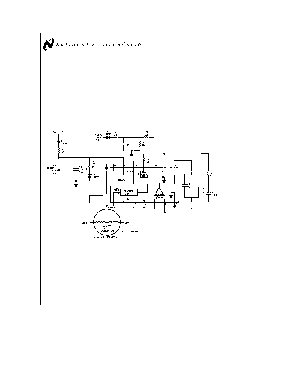
Typical Application
TL H 5263 1
FIGURE 1 Automotive Tachometer Application Circuit shown operates
with 4 cylinder engine and deflects meter pointer (270 ) at 6000 RPM
Order Number LM1819M or LM1819N
See NS Package Number M14A or N14A
TRW Type X463UW Polycarbonate Capacitor
RN60D Low TC Resistor (
g
100 ppm)
Components Required for Automotive Load Dump Protection
Available from FARIA Co
P O Box 983 Uncasville CT 06382
Tel 203-848-9271
C1995 National Semiconductor Corporation
RRD-B30M115 Printed in U S A
Absolute Maximum Ratings
If Military Aerospace specified devices are required
please contact the National Semiconductor Sales
Office Distributors for availability and specifications
Supply Voltage V
a
(pin 13)
20V
Power Dissipation (note 1)
1300 mW
Operating Temperature
b
40 C to
a
85 C
Storage Temperature
b
65 C to
b
150 C
Lead Temp (Soldering 10 seconds)
260 C
BV
CEO
20V
MIN
Electrical Characteristics
V
S
e
13 1V T
A
e
25 C unless otherwise specified
Symbol
Parameter
Pin(s)
Conditions
Min
Typ
Max
Units
I
S
Supply Current
13
Zero Input Frequency
65
mA
(See
Figure 1 )
V
REG
Regulator Voltage
11
I
REG
e
0 mA
8 1
8 5
8 9
V
Regulator Output Resistance
11
I
REG
e
0 mA to 3 mA
13 5
X
V
REF
Reference Voltage
4
I
REF
e
0 mA
1 9
2 1
2 3
V
Reference Output Resistance
4
I
REF
e
0 mA to 50 mA
5 3
kX
Norton Amplifier Mirror Gain
5 6
I
BIAS
j
20 mA
0 9
1 0
1 1
h
FE
NPN Transistor DC Gain
9 10
125
Function Generator Feedback
1
V
1
e
5 1V
1 0
mA
Bias Current
Drive Voltage Extremes
2 12
I
LOAD
e
20 mA
g
4
g
4 5
V
Sine and Cosine
Sine Output Voltage
2
V
8
e
V
REF
b
350
0
a
350
mV
with Zero Input
Function Generator Linearity
FSD
e
305
g
1 7
%FSD
k
Function Generator Gain
Meter Deflection DV
8
50 75
53 75
56 75
V
Note 1
For operation above 25 C the LM1819 must be derated based upon a 125 C maximum junction temperature and a thermal resistance of 76 C W which
applies for the device soldered in a printed circuit board and operating in a still-air ambient
Application Hints
AIR-CORE METER MOVEMENTS
Air-core meters are often favored over other movements as
a result of their mechanical ruggedness and their indepen-
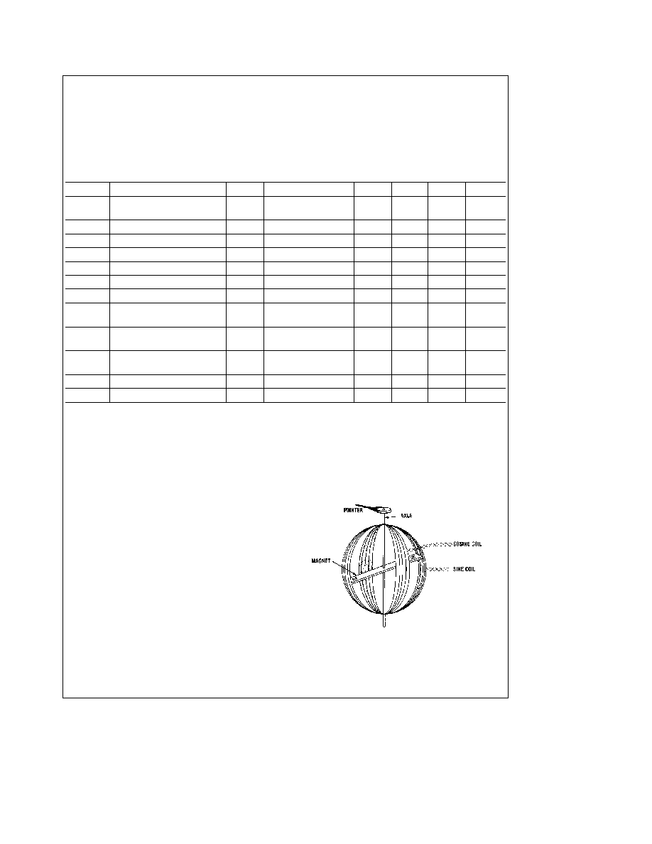
dence of calibration with age A simplified diagram of an air-
core meter is shown in
Figure 2 There are three basic
pieces a magnet and pointer attached to a freely rotating
axle and two coils each oriented at a right angle with re-
spect to the other The only moving part in this meter is the
axle assembly The magnet will tend to align itself with the
vector sum of H fields of each coil where H is the magnetic
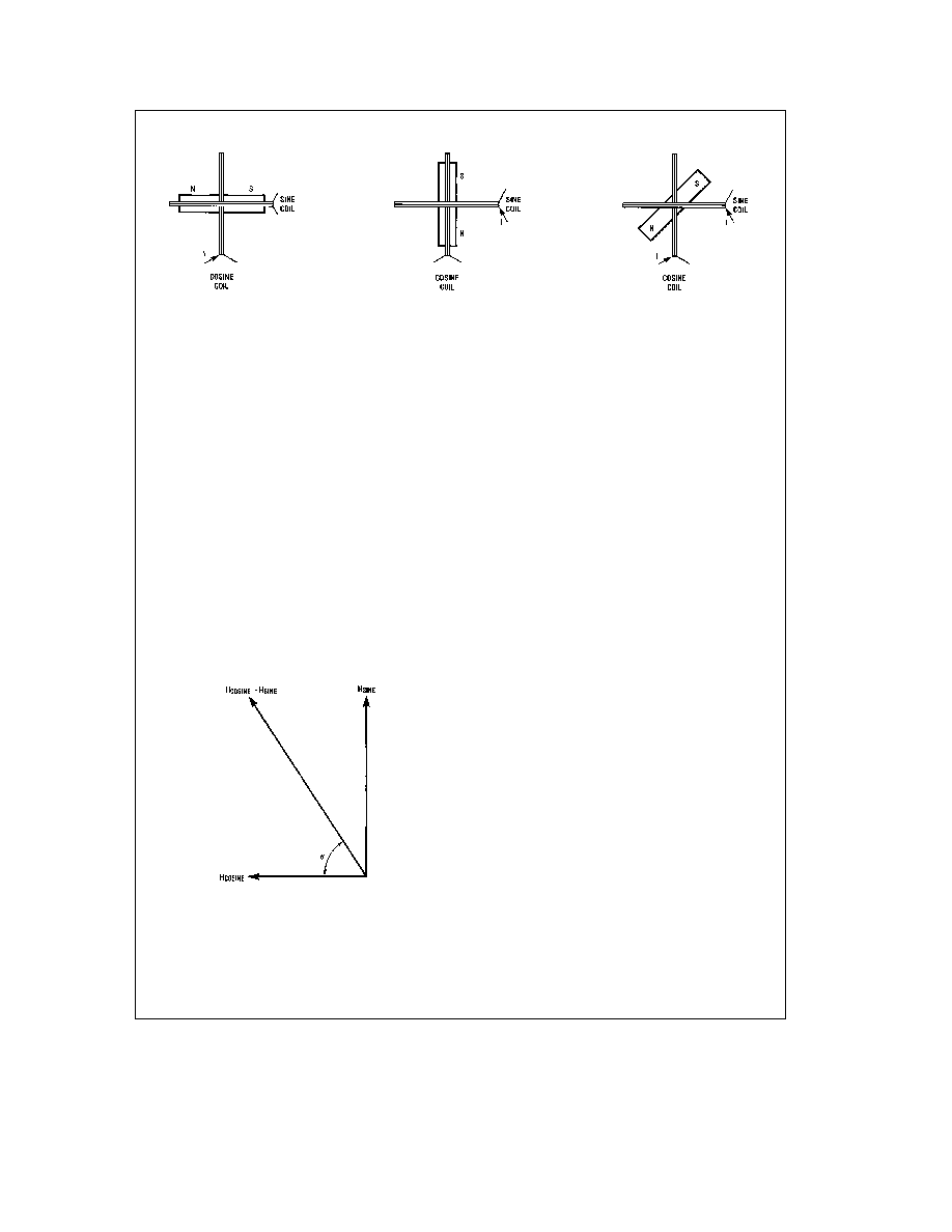
field strength vector If for instance a current passes
through the cosine coil (the reason for this nomenclature
will become apparent later) as shown in
Figure 3(a) the
magnet will align its magnetic axis with the coil's H field
Similarly a current in the sine coil (
Figure 3(b) ) causes the
magnet to align itself with the sine H field If currents are
applied simultaneously to both sine and cosine coils the
magnet will turn to the direction of the vector sum of the two
H
fields
(Figure 3(c)) H is proportional to the voltage applied
to a coil Therefore by varying both the polarity and magni-
tude of the coil voltages the axle assembly can be made to
rotate a full 360 The LM1819 is designed to drive the me-
ter through a minimum of 305
TL H 5263 2
FIGURE 2 Simplified Diagram of an Air Core Meter
2
Application Hints
(Continued)
TL H 5263 3
(c)
(b)
(a)
FIGURE 3 Magnet and pointer position are controlled by the H field generated by the two drive coils
In an air-core meter the axle assembly is supported by two
nylon bushings The torque exerted on the pointer is much
greater than that found in a typical d'Arsonval movement In
contrast to a d'Arsonval movement where calibration is a
function of spring and magnet characteristics air-core me-
ter calibration is only affected by the mechanical alignment
of the drive coils Mechanical calibration once set at manu-
facture can not change
Making pointer position a linear function of some input is a
matter of properly ratioing the drive to each coil The H field
contributed by each coil is a function of the applied current
and the current is a function of the coil voltage Our desired
result is to have i (pointer deflection measured in degrees)
proportional to an input voltage
i
e
kV
IN
1
where k is a constant of proportionality with units of de-
grees volt The vector sum of each coils' H field must follow
the deflection angle i We know that the axle assembly
always points in the direction of the vector sum of H
SINE
and H
COSINE
This direction (see
Figure 4 ) is found from the
formula
(i)
e
arctan
l
H
SINE
l l
H
COSINE
l
2
Recalling some basic trigonometry
(i)
e
arctan(sin (i)
cos(i ))
3
TL H 5263 4
FIGURE 4 The vector sum of H
COSINE
and H
SINE
points
in a direction i measured in a clockwise direction from
H
COSINE
Comparing 3 to 2 we see that if H
SINE
varies as the sine
of i and H
COSINE
varies as the cosine of i we will gener-
ate a net H field whose direction is the same as i And since
the axle assembly aligns itself with the net H field the point-
er will always point in the direction of i
THE LM1819
Included in the LM1819 is a function generator whose two
outputs are designed to vary approximately as the sine and
cosine of an input A minimum drive of
g
20 mA at
g
4V is
available at pins 2 (sine) and 12 (cosine) The common side
of each coil is returned to a 5 1V zener diode reference and
fed back to pin 1
For the function generator kj54 V (in equation 1) The
input (pin 8) is internally connected to the Norton amplifier's
output V
IN
as considered in equation 1 is actually the dif-
ference of the voltages at pins 8 (Norton output function
generator input) and 4 Typically the reference voltage at pin
4 is 2 1V Therefore
i
e
k(V
8
b
V
REF
)
e
54 (V
8
b
2 1)
4
As V
8
varies from 2 1V to 7 75V the function generator will
drive the meter through the chip's rated 305 range
Air-core meters are mechanically zeroed during manufac-
ture such that when only the cosine coil is driven the point-
er indicates zero degrees deflection However in some ap-
plications a slight trim or offset may be required This is
accomplished by sourcing or sinking a DC current of a few
microamperes at pin 4
A Norton amplifier is available for conditioning various input
signals and driving the function generator A Norton amplifi-
er was chosen since it makes a simple frequency to voltage
converter While the non-inverting input (pin 6) bias is at one
diode drop above ground the inverting input (5) is at 2 1V
equal to the pin 4 reference Mirror gain remains essentially
flat to I
MIRROR
e
5 mA The Norton amplifier's output (8) is
designed to source current into its load To bypass the Nor-
ton amplifier simply ground the non-inverting input tie the
inverting input to the reference and drive pin 8 (Norton out-
put function generator input) directly
An NPN transistor is included on chip for buffering and
squaring input signals Its usefulness is exemplified in
Fig-
ures 1
6 where an ignition pulse is converted to a rectan-
gular waveform by an RC network and the transistor The
emitter is internally connected to ground It is important not
to allow the base to drop below
b
5V
dc
as damage may
occur The 2 1V reference previously described is derived
from an 8 5V regulator at pin 11 Pin 11 is used as a stable
supply for collector loads and currents of up to 5 mA are
easily accommodated
3

Application Hints
(Continued)
TACHOMETER APPLICATION
A measure of the operating level of any motor or engine is
the rotational velocity of its output shaft In the case of an
automotive engine the crankshaft speed is measured using
the units ``revolutions per minute'' (RPM) It is possible to
indirectly measure the speed of the crankshaft by using the
signal present on the engine's ignition coil The fundamental
frequency of this signal is a function of engine speed and
the number of cylinders and is calculated (for a four-stroke
engine) from the formula
f e
n
0
120
(Hz)
(5)
where n
e
number of cylinders and
0
e
rotational velocity of
the crankshaft in RPM From this formula the maximum fre-
quency normally expected (for an 8 cylinder engine turning
4500RPM) is 300 Hz In certain specialized ignition systems
(motorcycles and some automobiles) where the coil wave-
form is operated at twice this frequency (
f e
0
60) These
systems are identified by the fact that multiple coils are used
in lieu of a single coil and distributor Also the coils have
two outputs instead of one
A typical automotive tachometer application is shown in
Fig-
ure 1 The coil waveform is filtered squared and limited by
the RC network and NPN transistor The frequency of the
pulse train at pin 9 is converted to a proportional voltage by
the Norton amplifier's charge pump configuration The igni-
tion circuit shown in
Figure 5 is typical of automotive sys-
tems The switching element ``S'' is opened and closed in
synchronism with engine rotation When ``S'' is closed en-
ergy is stored in Lp When opened the current in Lp diverts
from ``S'' into C The high voltage produced in Ls when ``S''
is opened is responsible for the arcing at the spark plug
The coil voltage (see
Figure 6 ) can be used as an input to
the LM1819 tachometer circuit This waveform is essentially
constant
duty cycle D4 rectifies this waveform thereby pre-
venting negative voltages from reaching the chip C4 and
R5 form a low pass filter which attenuates the high frequen-
cy ringing and R7 limits the input current to about 2 5mA
R6 acts as a base bleed to shut the transistor OFF when
``S'' is closed The collector is pulled up to the internal regu-
lator by R
REG
The output at pin 9 is a clean rectangular
pulse
Many ignition systems use magnetic hall effect or optical
sensors to trigger a solid state switching element at ``S ''
These systems (see the LM1815) typically generate pulses
of constant
width and amplitude suitable for driving the
charge pump directly
The charge pump circuit in
Figure 7 can be operated in two
modes constant input pulse width (C1 acts as a coupling
capacitor) and constant input duty cycle (C1 acts as a differ-
entiating capacitor) The transfer functions for these two
modes are quite diverse However deflection is always di-
rectly proportional to R2 and ripple is proportional to C2
The following variables are used in the calculation of meter
deflection
symbol
description
n
number of cylinders
0 0
IDLE
engine speed at redline and idle RPM
i
pointer deflection at redline degrees
e
charge pump input pulse width seconds
V
IN
peak to peak input voltages volts
Di
maximum desired ripple degrees
k
function generator gain degrees volt
f f
IDLE
input frequency at redline and idle Hz
Where the NPN transistor and regulator are used to create a
pulse V
IN
e
8 5V Acceptable ripple ranges from 3 to 10 de-
grees (a typical pointer is about 3 degrees wide) depending
on meter damping and the input frequency
The constant pulse width circuit is designed using the fol-
lowing equations
(1)
100 mA
k
V
IN
R1
k
3 mA
(2)
C
1
t
10e
R
1
(3)
R
2
e
R
1
i
V
IN
e
k
f
e
120R
1
i
V
IN
n
0
e
k
(4)
C
2
e
1
R
2
Di
f
IDLE
e
1
R
2
Di
n
0
IDLE
The constant duty cycle equations are as follows
R
REG
t
3 kX
R
1
s
V
IN
x10
4
b
R
REG
C
1
s
e
10(R
REG
a
R
1
)
R
Z
e
i
3 54n
0
C
1
e
i
425
f
C
1
C
2
e
425C
1
Di
The values in
Figure 1 were calculated with n
e
4
0
e
6000RPM
i
e
270
degrees
e
e
1
ms
V
IN
is
V
REG
b
0 7V and Di
e
3 degrees in the constant duty cycle
mode For distributorless ignitions these same equations will
apply if
0
60 is substituted for
f
4
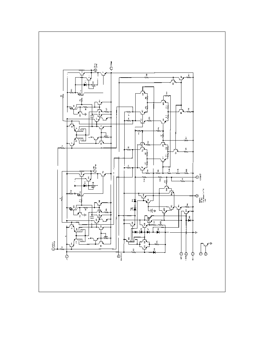
Equivalent Schematic
TLH5263
1
2
5