LM185-2.5/LM285-2.5/LM385-2.5
Micropower Voltage Reference Diode
General Description
The
LM185-2.5/LM285-2.5/LM385-2.5
are
micropower
2-terminal band-gap voltage regulator diodes. Operating
over a 20 µA to 20 mA current range, they feature exception-
ally low dynamic impedance and good temperature stability.
On-chip trimming is used to provide tight voltage tolerance.
Since the LM-185-2.5 band-gap reference uses only transis-
tors and resistors, low noise and good long term stability re-
sult.
Careful design of the LM185-2.5 has made the device ex-
ceptionally tolerant of capacitive loading, making it easy to
use in almost any reference application. The wide dynamic
operating range allows its use with widely varying supplies
with excellent regulation.
The extremely low power drain of the LM185-2.5 makes it
useful for micropower circuitry. This voltage reference can be
used to make portable meters, regulators or general purpose
analog circuitry with battery life approaching shelf life. Fur-
ther, the wide operating current allows it to replace older ref-
erences with a tighter tolerance part. For applications requir-
ing 1.2V see LM185-1.2.
The LM185-2.5 is rated for operation over a -55∞C to 125∞C
temperature range while the LM285-2.5 is rated -40∞C to
85∞C and the LM385-2.5 0∞C to 70∞C. The LM185-2.5/
LM285-2.5 are available in a hermetic TO-46 package and
the LM285-2.5/LM385-2.5 are also available in a low-cost
TO-92 molded package, as well as S.O. and SOT-23. The
LM185-2.5 is also available in a hermetic leadless chip car-
rier package.
Features
n
±
20 mV (
±
0.8%) max. initial tolerance (A grade)
n
Operating current of 20 µA to 20 mA
n
0.6
dynamic impedance (A grade)
n
Low temperature coefficient
n
Low voltage reference -- 2.5V
n
1.2V device and adjustable device also
available -- LM185-1.2 series and LM185 series,
respectively
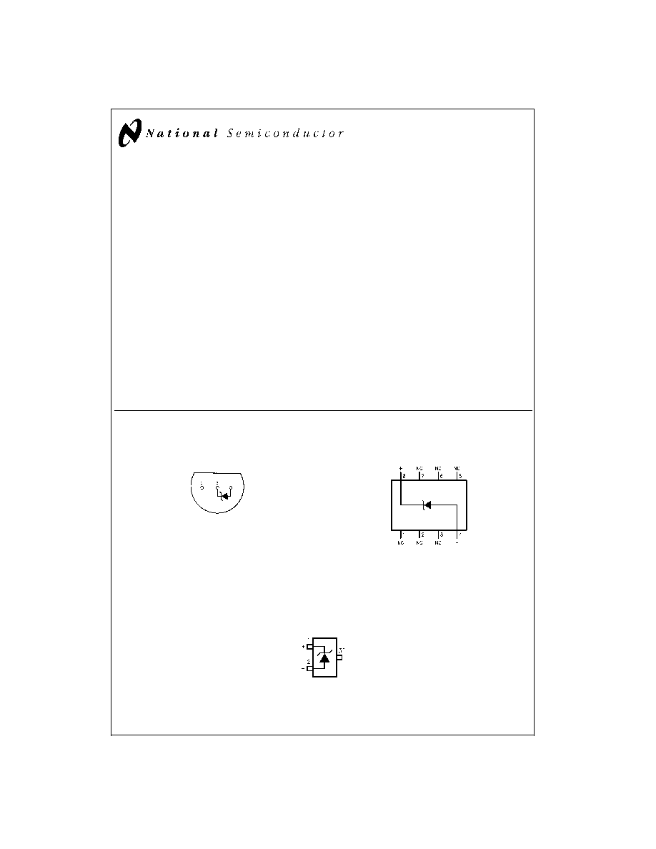
Connection Diagrams
TO-92
Plastic Package
DS005519-8
Bottom View
Order Number LM285Z-2.5,
LM285BXZ-2.5, LM285BYZ-2.5
LM385Z-2.5, LM385AXZ-2.5
LM385AYZ-2.5, LM385BZ-2.5,
LM385BXZ-2.5 or LM385BYZ-2.5
See NS Package Number Z03A
SO Package
DS005519-11
Order Number LM285M-2.5,
LM285BXM-2.5, LM285BYM-2.5
LM385M-2.5, LM385BM-2.5
LM385BXM-2.5 or LM385BYM-2.5
See NS Package Number M08A
SOT-23
DS005519-29
*
Pin 3 is attached to the Die Attach Pad (DAP) and should be connected to Pin 2 or left floating.
Order Number LM385M3-2.5
See NS Package Number MA03B
December 1999
LM185-2.5/LM285-2.5/LM385-2.5
Micropower
V
oltage
Reference
Diode
© 1999 National Semiconductor Corporation
DS005519
www.national.com
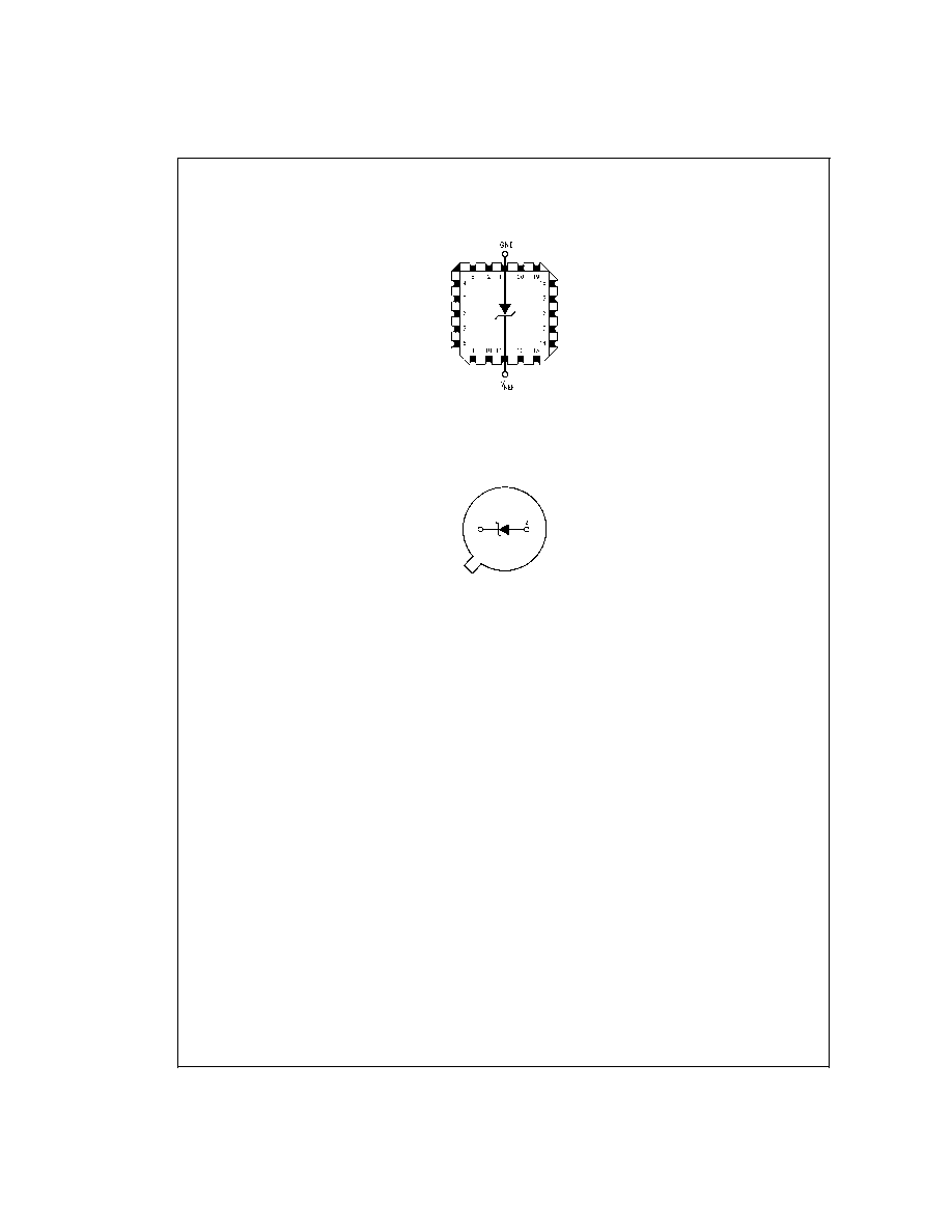
Connection Diagrams
(Continued)
LCC
Leadless Chip Carrier
DS005519-14
Order Number LM185E-2.5/883
See NS Package Number E20A
TO-46
Metal Can Package
DS005519-13
Bottom View
Order Number LM185H-2.5,
LM185H-2.5/883, LM185BXH-2.5,
LM185BXH-2.5/883, LM185BYH-2.5,
LM185BYH2.5/883, LM285H-2.5,
or LM285BYH-2.5
See NS Package Number H02A
LM185-2.5/LM285-2.5/LM385-2.5
www.national.com
2
Absolute Maximum Ratings
(Notes 1, 2)
If Military/Aerospace specified devices are required,
please contact the National Semiconductor Sales Office/
Distributors for availability and specifications.
Reverse Current
30 mA
Forward Current
10 mA
Operating Temperature Range (Note 3)
LM185-2.5
-55∞C to + 125∞C
LM285-2.5
-40∞C to + 85∞C
LM385-2.5
0∞C to 70∞C
Storage Temperature
-55∞C to + 150∞C
Soldering Information
TO-92 Package (10 sec.)
260∞C
TO-46 Package (10 sec.)
300∞C
SO and SOT Package
Vapor Phase (60 sec.)
215∞C
Infrared (15 sec.)
220∞C
See AN-450 "Surface Mounting Methods and Their Effect on
Product Reliability" for other methods of soldering surface
mount devices.
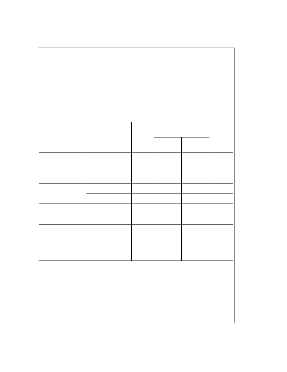
Electrical Characteristics
(Note 4)
Parameter
Conditions
Typ
LM385A-2.5
Units
(Limits)
LM385AX-2.5
LM385AY-2.5
Tested
Design
Limit
Limit
(Note 5)
(Note 6)
Reverse Breakdown
I
R
= 100 µA
2.500
2.480
V(Min)
Voltage
2.520
V(Max)
2.500
2.470
V(Min)
2.530
V(Max)
Minimum Operating
12
18
20
µA
Current
(Max)
Reverse Breakdown
I
MIN
I
R
1mA
1
1.5
mV
Voltage Change with
(Max)
Current
1 mA
I
R
20 mA
10
20
mV
(Max)
Reverse Dynamic
I
R
= 100 µA,
0.2
0.6
Impedance
f = 20 Hz
1.5
Wideband Noise (rms)
I
R
= 100 µA
120
µV
10 Hz
f
10 kHz
Long Term Stability
I
R
= 100 µA,
T = 1000 Hr,
20
ppm
T
A
= 25∞C
±
0.1∞C
Average Temperature
I
MIN
I
R
20 mA
Coefficient (Note 7)
X Suffix
30
ppm/∞C
Y Suffix
50
(Max)
All Others
150
LM185-2.5/LM285-2.5/LM385-2.5
www.national.com
3
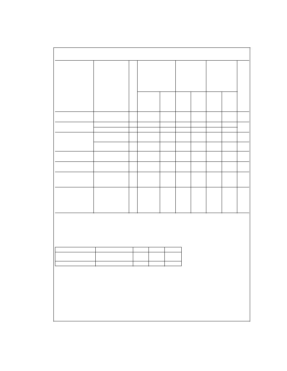
Electrical Characteristics
(Continued)
LM185-2.5
LM185BX-2.5
LM385B-2.5
LM185BY-2.5
LM385BX-2.5
LM385-2.5
Units
LM285-2.5
LM385BY-2.5
(Limit)
Parameter
Conditions
Typ
LM285BX-2.5
LM285BY-2.5
Tested
Design
Tested
Design
Tested
Design
Limit
Limit
Limit
Limit
Limit
Limit
(Note 5)
(Note 8)
(Note 6)
(Note 5)
(Note 6)
(Note 5)
(Note 6)
Reverse Breakdown
T
A
= 25∞C,
2.5
2.462
2.462
2.425
V(Min)
Voltage
20 µA
I
R
20 mA
2.538
2.538
2.575
V(Max)
Minimum Operating
Current
13
20
30
20
30
20
30
µA
(Max)
LM385M3-2.5
15
20
Reverse Breakdown
Voltage Change with
Current
20 µA
I
R
1 mA
1
1.5
2.0
2.5
2.0
2.5
mV
(Max)
1 mA
I
R
20 mA
10
20
20
25
20
25
mV
(Max)
Reverse Dynamic
I
R
= 100 µA,
1
Impedance
f = 20 Hz
Wideband Noise (rms)
I
R
= 100 µA,
120
µV
10 Hz
f
10 kHz
Long Term Stability
I
R
= 100 µA,
T = 1000 Hr,
20
ppm
T
A
= 25∞C
±
0.1∞C
Average Temperature
I
R
= 100 µA
Coefficient (Note 7)
X Suffix
30
30
ppm/∞C
Y Suffix
50
50
ppm/∞C
All Others
150
150
150
ppm/∞C
(Max)
Note 1: Absolute Maximum Ratings indicate limits beyond which damage to the device may occur. Operating Ratings indicate conditions for which the device is in-
tended to be functional, but do not guarantee specific performance limits. For guaranteed specifications and test conditions, see the Electrical Characteristics. The
guaranteed specifications apply only for the test conditions listed.
Note 2: Refer to RETS185H-2.5 for military specifications.
Note 3: For elevated temperature operation, T
J MAX
is:
LM185
150∞C
LM285
125∞C
LM385
100∞C
Thermal Resistance
TO-92
TO-46
SO-8
SOT-23
ja
(Junction to Ambient)
180∞C/W (0.4" Leads)
440∞C/W
165∞C/W
283∞C/W
170∞C/W (0.125" Leads)
jc
(Junction to Case)
N/A
80∞C/W
N/A
N/A
Note 4: Parameters identified with boldface type apply at temperature extremes. All other numbers apply at T
A
= T
J
= 25∞C.
Note 5: Guaranteed and 100% production tested.
Note 6: Guaranteed, but not 100% production tested. These limits are not used to calculate average outgoing quality levels.
Note 7: The average temperature coefficient is defined as the maximum deviation of reference voltage at all measured temperatures between the operating T
MAX
and T
MIN
, divided by T
MAX
≠T
MIN
. The measured temperatures are -55∞C, -40∞C, 0∞C, 25∞C, 70∞C, 85∞C, 125∞C.
Note 8: A military RETS electrical specification available on request.
LM185-2.5/LM285-2.5/LM385-2.5
www.national.com
4
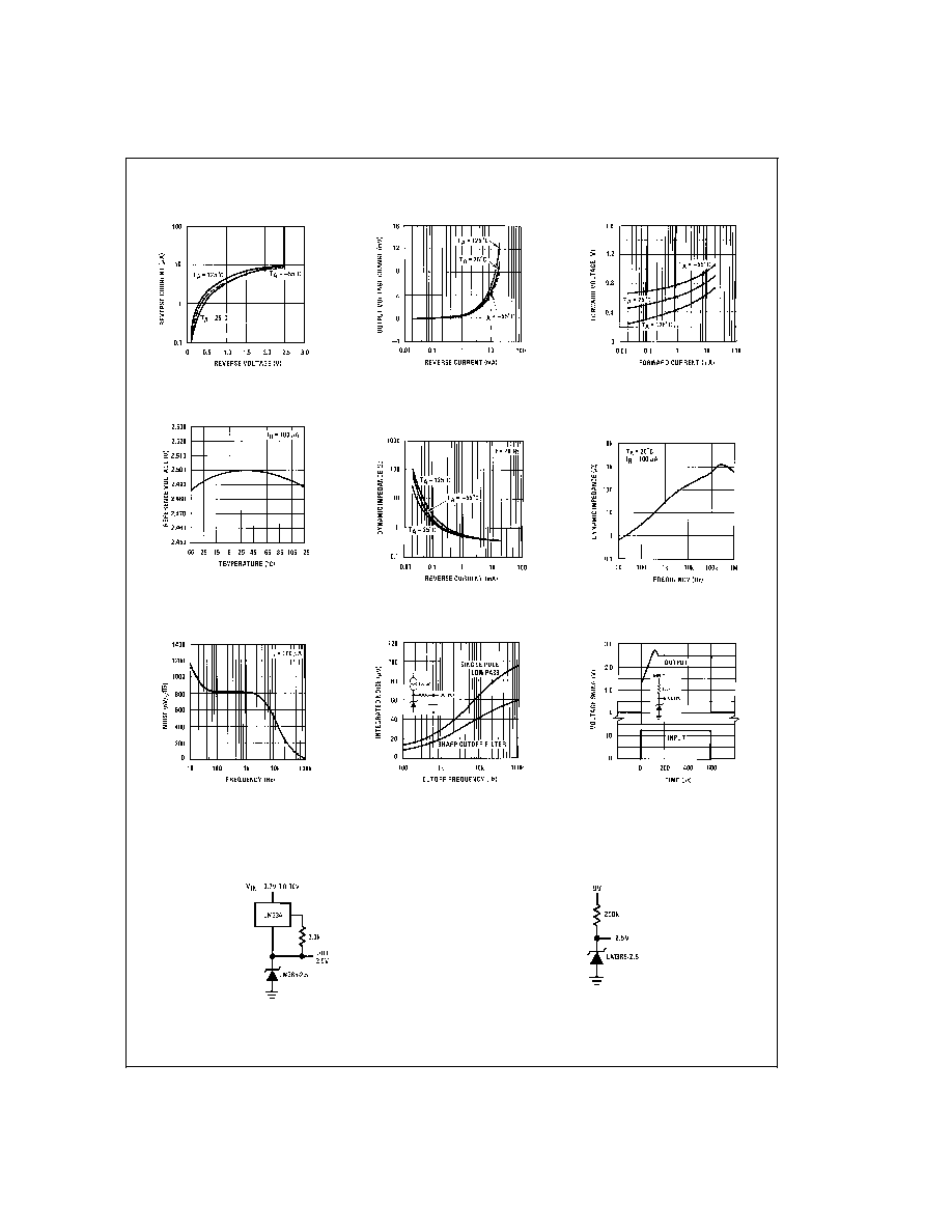
Typical Performance Characteristics
Applications
LM385-2.5 Applications
Reverse Characteristics
DS005519-15
Reverse Characteristics
DS005519-16
Forward Characteristics
DS005519-17
Temperature Drift
DS005519-18
Reverse Dynamic
Impedance
DS005519-19
Reverse Dynamic
Impedance
DS005519-20
Noise Voltage
DS005519-21
Filtered Output Noise
DS005519-22
Response Time
DS005519-23
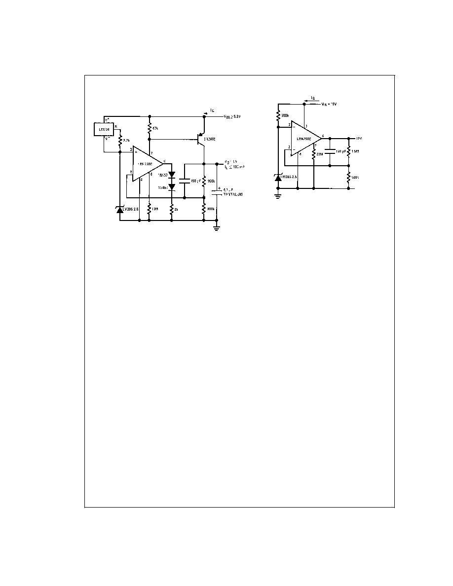
Wide Input Range Reference
DS005519-12
Micropower Reference from 9V Battery
DS005519-2
LM185-2.5/LM285-2.5/LM385-2.5
www.national.com
5
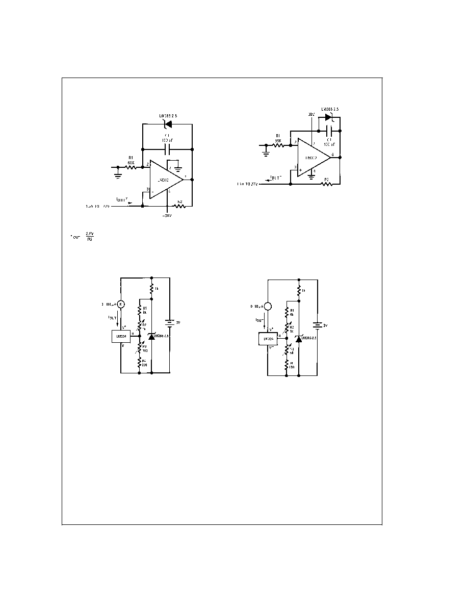
LM385-2.5 Applications
(Continued)
Micropower 5V Reference (Note 9)
DS005519-9
Note 9: I
Q
40 µA
Micropower 10V Reference (Note 10)
DS005519-10
Note 10: I
Q
30 µA standby current
LM185-2.5/LM285-2.5/LM385-2.5
www.national.com
6
LM385-2.5 Applications
(Continued)
Precision 1 µA to 1 mA Current Sources
DS005519-24
DS005519-25
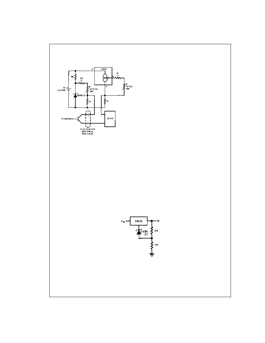
METER THERMOMETERS
0∞C≠100∞C Thermomemter
DS005519-26
Calibration
1.
Short LM385-2.5, adjust R3 for I
OUT
=temp at 1µA/∞K
2.
Remove short, adjust R2 for correct reading in centi-
grade
0∞F≠50∞F Thermomemter
DS005519-27
Calibration
1.
Short LM385-2.5, adjust R3 for I
OUT
=temp at 1.8 µA/∞K
2.
Remove short, adjust R2 for correct reading in ∞F
LM185-2.5/LM285-2.5/LM385-2.5
www.national.com
7
LM385-2.5 Applications
(Continued)
Seebeck
Voltage
Voltage
Thermocouple
Co-
R1
R2
Across R1
Across R2
Type
efficient
(
)
(
)
@
25∞C
(mV)
(
µ
V/∞C)
(mV)
J
52.3
523 1.24k
15.60
14.32
T
42.8
432
1k
12.77
11.78
K
40.8
412 953
12.17
11.17
S
6.4
63.4 150
1.908
1.766
Typical supply current 50 µA
Micropower Thermocouple Cold Junction
Compensator
DS005519-6
Adjustment Procedure
1.
Adjust TC ADJ pot until voltage across R1 equals Kelvin
temperature multiplied by the thermocouple Seebeck
coefficient.
2.
Adjust zero ADJ pot until voltage across R2 equals the
thermocouple Seebeck coefficient multiplied by 273.2.
Improving Regulation of Adjstable Regulators
DS005519-7
LM185-2.5/LM285-2.5/LM385-2.5
www.national.com
8

Schematic Diagram
DS005519-1
LM185-2.5/LM285-2.5/LM385-2.5
www.national.com
9
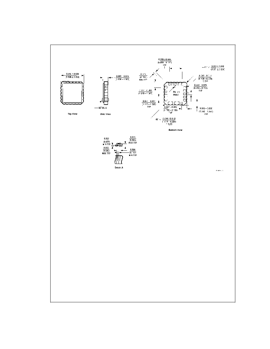
Physical Dimensions
inches (millimeters) unless otherwise noted
Order Number LM185E-2.5/883
NS Package Number E20A
LM185-2.5/LM285-2.5/LM385-2.5
www.national.com
10
Physical Dimensions
inches (millimeters) unless otherwise noted (Continued)
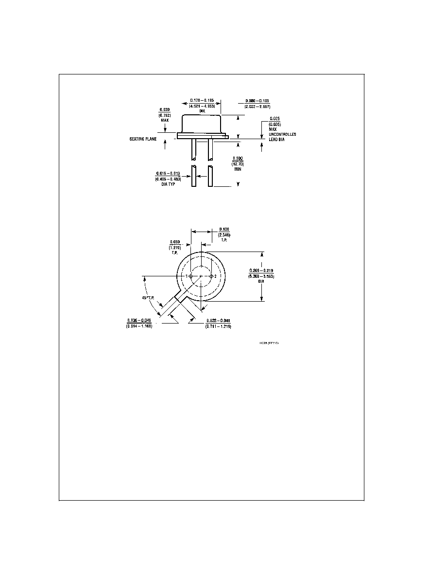
TO-46 Metal Can Package (H)
Order Number LM185H-2.5, LM185H-2.5/883, LM185BXH-2.5, LM185BXH-2.5/883,
LM185BYH-2.5, LM185BYH-2.5/883, LM285H-2.5, or LM285BYH-2.5
NS Package Number H02A
LM185-2.5/LM285-2.5/LM385-2.5
www.national.com
11
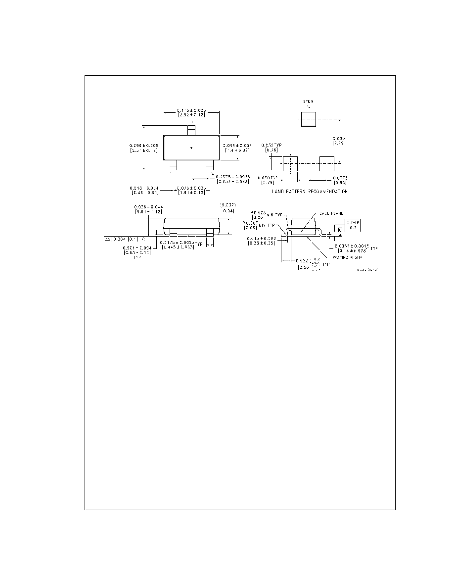
Physical Dimensions
inches (millimeters) unless otherwise noted (Continued)
SOT-23 Package (M3)
Order Number LM385M3-2.5
NS Package Number MA03B
LM185-2.5/LM285-2.5/LM385-2.5
www.national.com
12

Physical Dimensions
inches (millimeters) unless otherwise noted (Continued)
Small Outline (SO-8) Package (M)
Order Number LM285M-2.5, LM285BXM-2.5, LM285BYM-2.5,
LM385M-2.5, LM385BM-2.5, LM385BXM-2.5 or LM385BYM-2.5
NS Package Number M08A
LM185-2.5/LM285-2.5/LM385-2.5
www.national.com
13
Physical Dimensions
inches (millimeters) unless otherwise noted (Continued)
LIFE SUPPORT POLICY
NATIONAL'S PRODUCTS ARE NOT AUTHORIZED FOR USE AS CRITICAL COMPONENTS IN LIFE SUPPORT
DEVICES OR SYSTEMS WITHOUT THE EXPRESS WRITTEN APPROVAL OF THE PRESIDENT AND GENERAL
COUNSEL OF NATIONAL SEMICONDUCTOR CORPORATION. As used herein:
1. Life support devices or systems are devices or
systems which, (a) are intended for surgical implant
into the body, or (b) support or sustain life, and
whose failure to perform when properly used in
accordance with instructions for use provided in the
labeling, can be reasonably expected to result in a
significant injury to the user.
2. A critical component is any component of a life
support device or system whose failure to perform
can be reasonably expected to cause the failure of
the life support device or system, or to affect its
safety or effectiveness.
National Semiconductor
Corporation
Americas
Tel: 1-800-272-9959
Fax: 1-800-737-7018
Email: support@nsc.com
National Semiconductor
Europe
Fax: +49 (0) 1 80-530 85 86
Email: europe.support@nsc.com
Deutsch Tel: +49 (0) 1 80-530 85 85
English
Tel: +49 (0) 1 80-532 78 32
FranÁais Tel: +49 (0) 1 80-532 93 58
Italiano
Tel: +49 (0) 1 80-534 16 80
National Semiconductor
Asia Pacific Customer
Response Group
Tel: 65-2544466
Fax: 65-2504466
Email: sea.support@nsc.com
National Semiconductor
Japan Ltd.
Tel: 81-3-5639-7560
Fax: 81-3-5639-7507
www.national.com
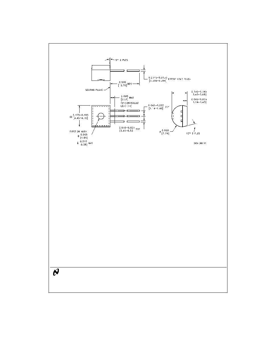
TO-92 Plastic Package (Z)
Order Number LM285Z-2.5, LM285BXZ-2.5, LM285BYZ-2.5,
LM385Z-2.5, LM385AXZ-2.5, LM385AYZ-2.5,
LM385BZ-2.5, LM385BXZ-2.5 or LM385BYZ-2.5
NS Package Number Z03A
LM185-2.5/LM285-2.5/LM385-2.5
Micropower
V
oltage
Reference
Diode
National does not assume any responsibility for use of any circuitry described, no circuit patent licenses are implied and National reserves the right at any time without notice to change said circuitry and specifications.