TL H 7909
LM1868
AMFM
Radio
System
February 1995
LM1868 AM FM Radio System
General Description
The combination of the LM1868 and an FM tuner will pro-
vide all the necessary functions for a 0 5 watt AM FM radio
Included in the LM 1868 are the audio power amplifier FM
IF and detector and the AM converter IF and detector
The device is suitable for both line operated and 9V battery
applications
Features
Y
DC selection of AM FM mode
Y
Regulated supply
Y
Audio amplifier bandwidth decreased in AM mode
reducing amplifier noise in the AM band
Y
AM converter AGC for excellent overload
characteristics
Y
Low current internal AM detector for low tweet radiation
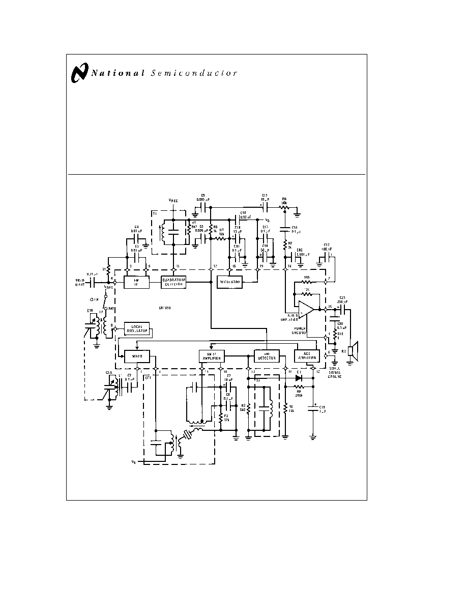
Block Diagram
TL H 7909 1
Order Number LM1868N
See NS Package Number N20A
Note
See table for coil data
C1995 National Semiconductor Corporation
RRD-B30M115 Printed in U S A
Absolute Maximum Ratings
If Military Aerospace specified devices are required
please contact the National Semiconductor Sales
Office Distributors for availability and specifications
Supply Voltage (Pin 19)
15V
Package Dissipation
2 0W
Above T
A
e
25 C Derate Based on
T
J(MAX)
e
150 C and i
JA
e
60 C W
Storage Temperature Range
b
55 C to
a
150 C
Operating Temperature Range
0 C to
a
70 C
Lead Temperature (Soldering 10 sec )
260 C
Electrical Characteristics
Test Circuit T
A
e
25 C V
S
e
9V R
L
e
8X (unless otherwise noted)
Parameter
Conditions
Min
Typ
Max
Units
STATIC CHARACTERISTICS
e
AM
e
0 e
FM
e
0
Supply Current
AM Mode S1 in Position 1
22
30
mA
Regulator Output Voltage (Pin 16)
3 5
3 9
4 8
V
Operating Voltage Range
4 5
15
DYNAMIC CHARACTERISTICS
AM MODE
f
AM
e
1 MHz f
mod
e
1 kHz 30% Modulation S1 in Position 1 P
O
e
50 mW unless noted
Maximum Sensitivity
Measure e
AM
for P
O
e
50 mW
8
16
m
V
Maximum Volume
Signal-to-Noise
e
AM
e
10 mV
40
50
dB
Detector Output
e
AM
e
1 mV
40
60
85
mV
Measure at Top of Volume Control
Overload Distortion
e
AM
e
50 mV 80% Modulation
2
10
%
Total Harmonic Distortion (THD)
e
AM
e
10 mV
1 1
2
%
DYNAMIC CHARACTERISTICS
FM MODE
f
FM
e
10 7 MHz f
mod
e
400 Hz Df
e
g
75 kHz P
O
e
50 mW S1 in Position 1
b
3 dB Limiting Sensitivity
15
45
m
V
Signal-to-Noise Ratio
e
FM
e
10 mV
50
64
dB
Detector Output
e
FM
e
10 mV Df
e
g
22 5 kHz
40
60
85
mV
Measure at Top of Volume Control
AM Rejection
e
FM
e
10 mV 30% AM Modulation
40
50
dB
Total Harmonic Distortion (THD)
e
FM
e
10 mV
1 1
2
%
DYNAMIC CHARACTERISTICS
AUDIO AMPLIFIER ONLY
f
e
1 kHz e
AM
e
0 e
FM
e
0 S1 in Position 2
Power Output
THD
e
10% R
L
8X
V
S
e
6V
250
325
mW
V
S
e
9V
500
700
mW
Bandwidth
AM Mode P
O
e
50 mW
11
kHz
FM Mode P
O
e
50 mW
22
kHz
Total Harmonic Distortion (THD)
P
O
e
50 mW FM Mode
0 2
%
Voltage Gain
41
dB
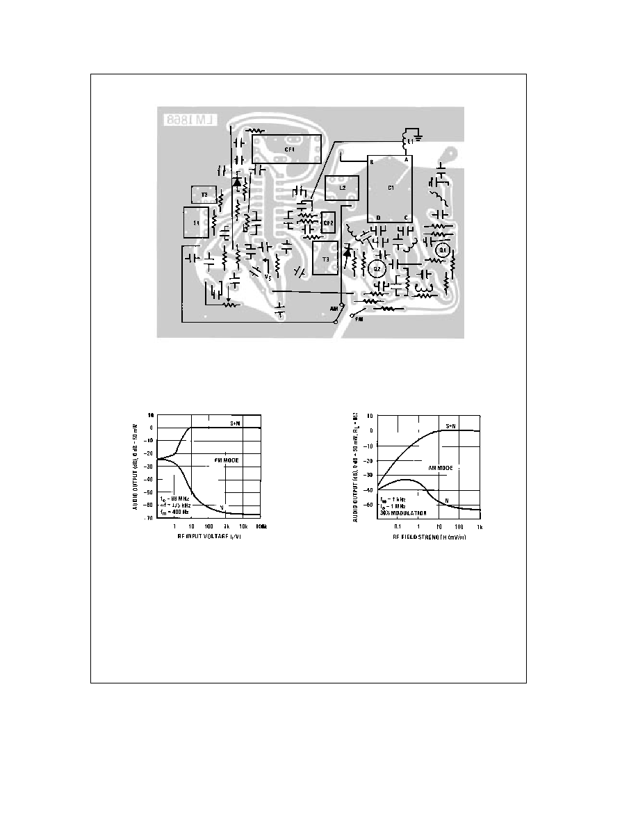
Typical Performance Characteristics
(Test Circuit) All curves are measured at audio output
vs Voltage
Quiescent Supply Current
FM Limiting Characteristics
FM IF AM Rejection
TL H 7909 2
2
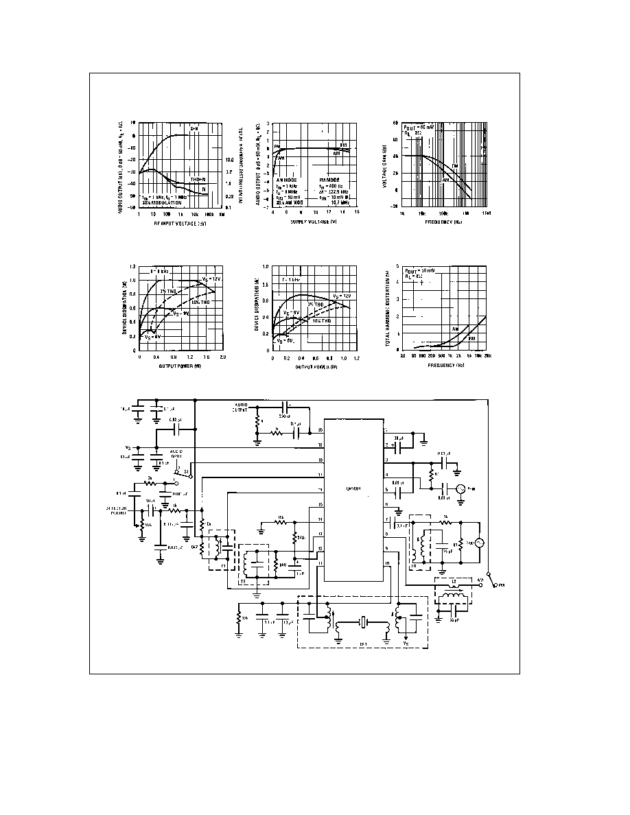
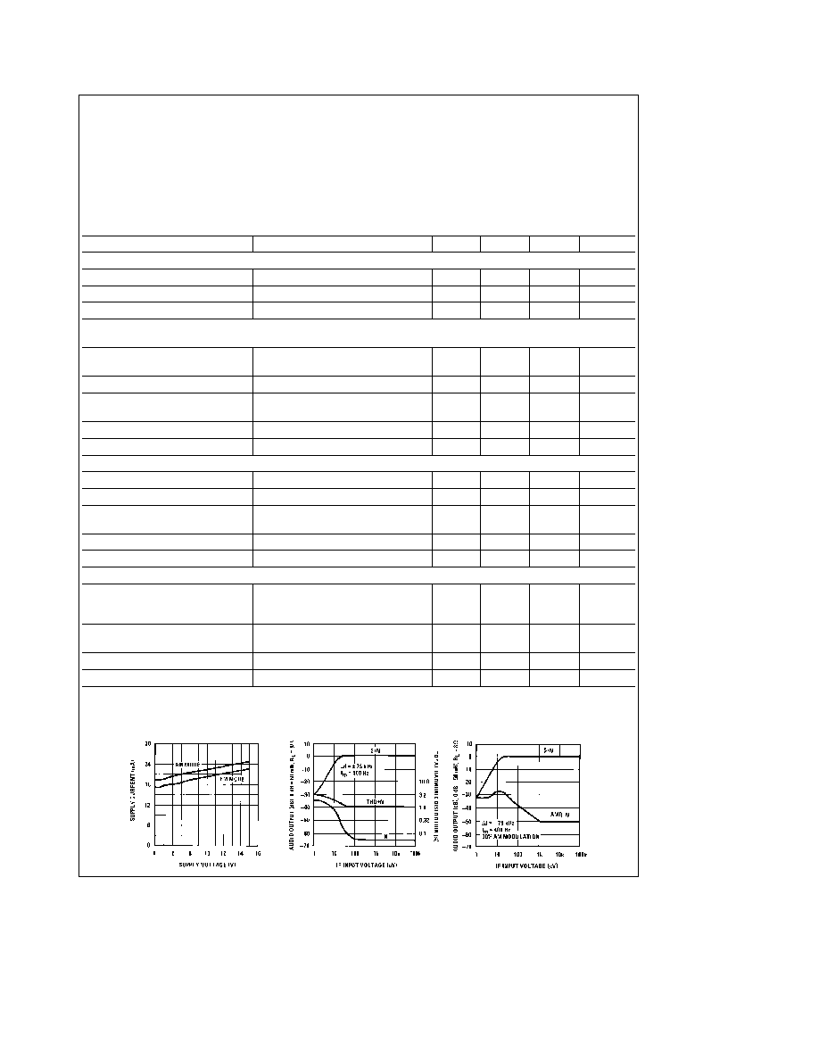
Typical Performance Characteristics
(Continued)
All curves are measured at audio output (Test Circuit)
AM Characteristics
Recovered Audio vs Supply
Amplifier Only
Gain vs Frequency Audio
Output R
L
e
8X
Power Dissipation vs Power
Out R
L
e
16X
Power Dissipation vs Power
Audio Amplifier Only
Distortion vs Frequency
TL H 7909 3
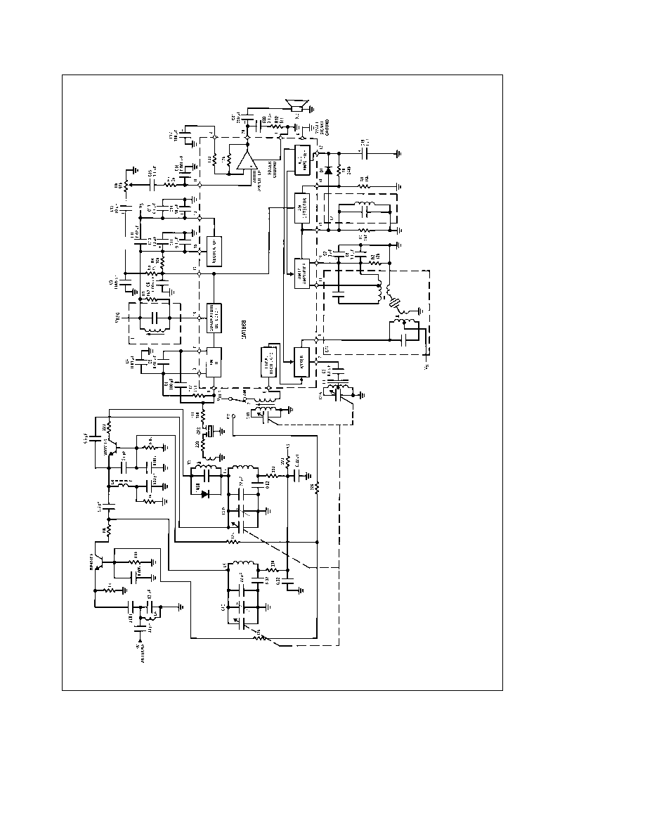
Test Circuit
Note
See table for coil data
TL H 7909 4
3