 | –≠–ª–µ–∫—Ç—Ä–æ–Ω–Ω—ã–π –∫–æ–º–ø–æ–Ω–µ–Ω—Ç: LM1946N | –°–∫–∞—á–∞—Ç—å:  PDF PDF  ZIP ZIP |

TL H 8707
LM1946
OverUnder
Current
Limit
Diagnostic
Circuit
February 1993
LM1946 Over Under Current Limit Diagnostic Circuit
General Description
The LM1946 provides the industrial or automotive system
designer with over or under current limit detection superior
to that of ordinary transistor or comparator-based circuits
Each of the five independent comparators can be used to
monitor a separate load as either an over current or under
current limit detector Two comparators monitoring a single
load can function as a current window monitor
Current is sensed by monitoring the voltage drop across the
wiring harness pc board trace or external sense resistor
that feeds the load
Provisions for compensating the user set limits for wiring
harness resistance variations over temperature and supply
voltage variations are also available
When a limit is reached in one of the comparators it turns
on its output which can drive an external LED or microproc-
essor
One side of the load can be grounded (not possible with
ordinary comparator designs) which is important for auto-
motive systems
Features
Y
Five independent comparators
Y
Capable of 20 mA per output
Y
Low power drain
Y
User set input threshold voltages
Y
Reverse battery protection
Y
60V load dump protection on supply and all inputs
Y
Input common mode range exceeds V
CC
Y
Short circuit protection
Y
Thermal overload protection
Y
Prove-out test pin
Y
Available in plastic DIP and SO packages
Applications
Y
Lamp fault detector
Y
Motor stall detector
Y
Power supply bus monitoring
Typical Application Circuit
Lamp Fault Detector
(I
L
l
1A)
TL H 8707 ≠ 2
FIGURE 1
C1995 National Semiconductor Corporation
RRD-B30M115 Printed in U S A

Absolute Maximum Ratings
If Military Aerospace specified devices are required
please contact the National Semiconductor Sales
Office Distributors for availability and specifications
Supply Voltage (V
CC
and Input Pins)
Survival Voltage (T
s
100 ms)
b
50V to
a
60V
Operational Voltage
9V to 26V
Internal Power Dissipation (Note 1)
Internally Limited
Output Short Circuit to Ground or V
CC
Continuous
Operating Temperature Range (T
A
)
b
40 C to
a
85 C
Maximum Junction Temperature
a
150 C
Storage Temperature Range
b
65 C to
a
150 C
Lead Temperature (Soldering 10 sec )
a
260 C
ESD Susceptibility (Note 3)
600V
Electrical Characteristics
9V
s
V
CC
s
16V Iset
e
20 mA T
j
e
25 C (unless otherwise specified)
Parameter
Conditions
Min
Typ
Max
Units
Quiescent Current
All Outputs ``Off''
1 40
3 00
mA
dc
Reference Voltage
I
ref
e
10 mA
5 8
6 4
7 0
V
dc
Reference Voltage
9V
s
V
CC
s
16V I
ref
e
10 mA
g
5
g
50
mV
dc
Line Regulation
Iset Voltage
Iset
e
20 mA
1 20
1 40
1 60
V
dc
Input Offset Voltage
At Output Switch Point V
O
e
2V
g
1 0
g
5 0
mV
dc
9V
s
V
CM
s
16V
Input Offset Current
I
IN(a)
b
I
IN(b)
9V
s
V
CM
s
16V
g
0 10
g
1 00
m
A
dc
Input Bias Current
I
IN(a)
or I
IN(b)
9V
s
V
CM
s
16V
18 00
20 00
22 00
m
A
dc
Input Common Mode
4 00
26 0
V
dc
Voltage Range
Maximum Positive
Either Input T
s
100 ms
60
70
V
Input Transient
Maximum Negative
Either Input T
s
100 ms
b
50
b
60
V
Input Transient
Output Saturation
I
O
e
2 mA 9V
s
V
CC
s
16V
0 80
1 00
V
dc
Voltage
I
O
e
10 mA 9V
s
V
CC
s
16V
1 00
1 20
V
dc
Output Short Circuit
V
O
e
0V
dc
Comparator ``ON''
20
45
120 0
mA
dc
Current
Output Leakage Current
V
O
e
0V
dc
Comparator ``Off''
0 01
1 00
m
A
dc
Test Threshold
At Switch Point on Any Output
0 80
1 25
2 00
V
dc
Voltage
V
O
e
2V (Note 2)
Test Threshold
0 2
m
A
dc
Current
Note 1
Thermal resistance from junction to ambient is typically 53 C W (board mounted)
Note 2
The test pin is an active high input i e all five will be forced high when this pin is driven high
Note 3
C
ESD
e
100 pF R
ESD
e
1 5k
2
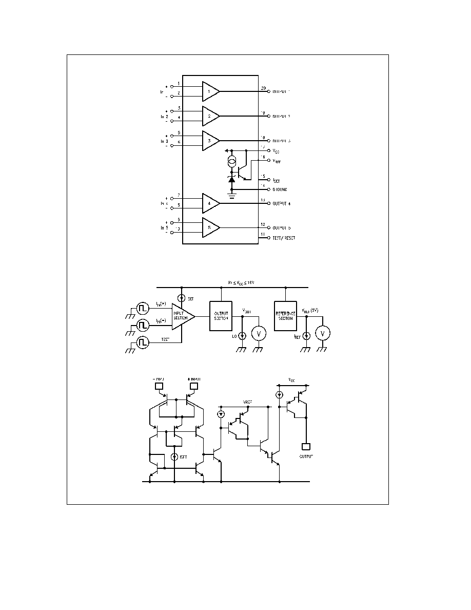
Connection Diagram
TL H 8707 ≠ 20
Order Number LM1946N or LM1946M
See NS Package Number M20B or N20A
Typical Test Circuit
TL H 8707 ≠ 23
Simplified Comparator Schematic
TL H 8707 ≠ 24
3
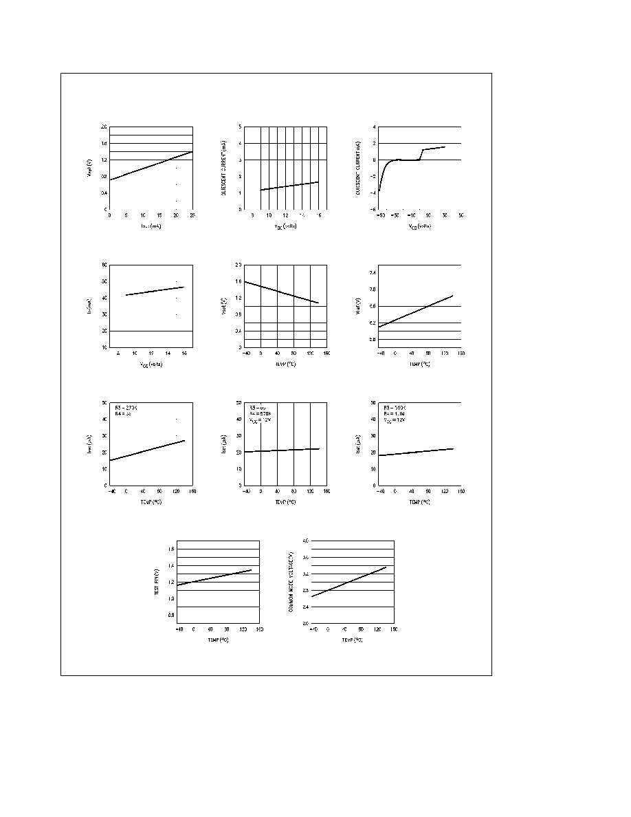
Typical Performance Characteristics
V
sat
vs I
O
vs V
CC
Quiescent Current
vs V
CC
Quiescent Current
Peak I
O
vs V
CC
V
set
vs Temperature
V
ref
vs Temperature
Iset vs Temperature
Iset vs Temperature
Iset vs Temperature
Test Threshold
Common Mode Lower Limit
TL H 8707 ≠ 4
4
Application Hints
THEORY OF OPERATION UNDER-CURRENT LIMIT
DETECTOR
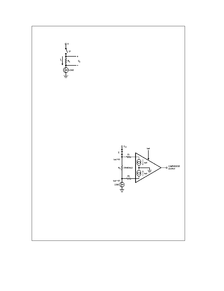
TL H 8707 ≠ 6
Lamp Fault Detector
FIGURE 3 Equivalent Automotive Lamp Circuit
The diagram of
Figure 3 represents the typical lamp circuit
found in most automobiles Switch S1 represents a dash-
board switch discrete power device relay and or flasher
circuit used for turn signals Sense resistor R
s
can be an
actual circuit component (such as a 0 1X 1W carbon resis-
tor) or it can represent the resistance of some or all of the
wiring harness The load represented here as a single bulb
can just as easily be two or more bulbs in parallel such as
front and rear parking lights or left and right highbeams etc
One of the easiest methods to electronically monitor proper
bulb operation is to sense the voltage developed across R
s
by the bulb current I
L
If a fault occurs due to an open bulb
filament the load current and sense voltage V
S
drop to
zero (or to half their former values in the case of two bulbs
wired in parallel) A comparator circuit can then monitor this
sense voltage and alert the system or system user (e g
power an LED) if this sense voltage drops below a predeter-
mined level (defined as the threshold voltage)
Typical sense voltages range from tens to hundreds of milli-
volts Not only does this sense voltage vary nonlinearly with
the battery voltage it may vary significantly with ambient
temperature depending on the temperature coefficient (TC)
of the sense resistor or wiring harness Since these nonlin-
ear characteristics can vary from system to system and
sometimes even within a single system provisions must be
made to accommodate them There are two general meth-
odologies to accomplish this
The first method uses only one bulb per monitoring circuit A
sense resistor is selected to give 50 ≠ 100 mV of sense volt-
age in an operational circuit and a comparator threshold
detecting voltage of approximately 10 mV is set Even if
component tolerances battery line variations and tempera-
ture coefficients cause the sense voltage to vary 3 1 or
more circuit operation will not be affected
The second method must be used if two or more bulbs are
wired in parallel and it is necessary to detect if any single
lamp fails This is often desirable as it reduces the number
of comparators and displays and system cost by at least a
factor of two In this case the sense voltage will drop by
only half (or less) of it's original value For example a nomi-
nal 100 mV drop across the sense resistor will drop to
50 mV if one of two bulbs fail Therefore a threshold detec-
tion voltage between 50 and 100 mV is required (since a
10 mV threshold would alert the system only if both bulbs
failed) Yet a fixed threshold of 75 mV may not work if the
nominal 100 mV sense voltage can vary 3 1 due to the fac-
tors mentioned earlier What is required is a comparator with
a threshold-detecting voltage that tracks the nominal sense
voltage as battery line and ambient temperature change
Thus while the sense voltage may nominally be anywhere
from 50 to 150 mV the threshold voltage will always be
roughly 75% of it or 37 mV to 112 mV and will detect the
failure of either of two bulbs
The LM1946 integrated circuit contains five comparators es-
pecially designed for lamp monitoring requirements Since
all lamps in a system share the same battery voltage and
ambient temperature accommodations for these variations
need to be made only once at the IC and each threshold of
the five comparators then tracks these variations
SETTING THE COMPARATOR THRESHOLD VOLTAGE
The threshold voltage at which the comparator output
changes state is user-set in order to accommodate the
many possible system designs The input bias currents are
purposely high to accomplish this and are each equal to the
user-set current into the Iset pin (more on this later) Typi-
cally around 20 mA the effect of this across the sense resis-
tor R
s
compared to a typical load measured in amps is negli-
gible and can be ignored However when resistors R1 and
R2
(Figure 4) are added to the circuit a shift in the threshold
voltage is effected This occurs since each input has been
affected by different IR drops The LM1946 behaves like
any other comparator in that the output switches when the
input voltage at the IC pins is zero millivolts (ignoring offset
voltage for the moment) If the output therefore has just
switched states due to just the right threshold voltage
across the sense resistor then the sum of voltages around
the resistor loop should equal zero
TL H 8707 ≠ 9
Vthrshld
e
Iset (R1
b
R2)
FIGURE 4 Input Bias Current
Vthrshld
a
Iset
R2
b
Voffset
b
Iset
R1
e
0
Assuming Voffset m Vthrshld
Vthrshld
e
Iset
R1
b
Iset
R2
Vthrshld
e
Iset (R1
b
R2)
5