
LM95241
Dual Remote Diode Temperature Sensor with SMBus
Interface and TruTherm
TM
Technology (65nm/90nm)
General Description
The LM95241 is a precision dual remote diode temperature
sensor (RDTS) that uses National's TruTherm technology.
The 2-wire serial interface of the LM95241 is compatible with
SMBus 2.0. The LM95241 can sense three temperature
zones, it can measure the temperature of its own die as well
as two diode connected transistors. The LM95241 includes
digital filtering and an advanced input stage that includes
analog filtering and TruTherm technology that reduces
processor-to-processor non-ideality spread. The diode con-
nected transistors can be a "thermal diode" as found in Intel
and AMD processors or can simply be a diode connected
MMBT3904 transistor. TruTherm technology allows accurate
measurement of "thermal diodes" found on small geometry
processes such as 90nm and 65nm. The LM95241 supports
user selectable thermal diode non-ideality of either a Pen-
tium
Æ
processor on 90nm or 65nm process or 2N3904.
The LM95241 resolution format for remote temperature
readings can be programmed to be 11-bits signed or un-
signed with the digital filtering disabled. When the filtering is
enabled the resolution increases to 13-bits signed or un-
signed. In the unsigned mode the LM95241 remote diode
readings can resolve temperatures above 127∞C. Local tem-
perature readings have a resolution of 9-bits plus sign.
Features
n
Accurately senses die temperature of remote ICs or
diode junctions
n
Uses TruTherm technology for precision "thermal diode"
temperature measurement
n
Thermal diode input stage with analog filtering
n
Thermal diode digital filtering
n
Intel Pentium processor on 65nm or 90nm process or
2N3904 non-ideality selection
n
Remote diode fault detection
n
On-board local temperature sensing
n
Remote temperature readings without digital filtering:
-- 0.125 ∞C LSb
-- 10-bits plus sign or 11-bits programmable resolution
-- 11-bits resolves temperatures above 127 ∞C
n
Remote temperature readings with digital filtering:
-- 0.03125 ∞C LSb with filtering
-- 12-bits plus sign or 13-bits programmable resolution
-- 13-bits resolves temperatures above 127 ∞C
n
Local temperature readings:
-- 0.25 ∞C
-- 9-bits plus sign
n
Status register support
n
Programmable conversion rate allows user optimization
of power consumption
n
Shutdown mode one-shot conversion control
n
SMBus 2.0 compatible interface, supports TIMEOUT
n
8-pin MSOP package
Key Specifications
j
Remote Diode Temperature Accuracy
T
A
=20∞C to 40∞C, T
D
=45∞C to 85∞C
±
1.25 ∞C (max)
T
A
=0∞C to 85∞C, T
D
=25∞C to 140∞C
±
2.5 ∞C (max)
j
Local Temperature Accuracy
T
A
=0∞C to 85∞C
±
3.0 ∞C (max)
j
Supply Voltage
3.0 V to 3.6 V
j
Average Supply Current
471 µA (typ)
Applications
n
Processor/Computer System Thermal Management
(e.g. Laptop, Desktop, Workstations, Server)
n
Electronic Test Equipment
n
Office Electronics
Connection Diagram
MSOP-8
20199702
TOP VIEW
TruTherm
TM
is a trademark of National Semiconductor Corporation.
I2C
Æ
is a registered trademark of Philips Corporation.
Pentium
Æ
is a registered trademark of Intel Corporation.
ADVANCE INFORMATION
August 2006
LM95241
Dual
Remote
Diode
T
emperature
Sensor
with
SMBus
Interface
and
T
ruTherm
T
echnology
(65nm/90nm)
© 2006 National Semiconductor Corporation
DS201997
www.national.com

Ordering Information
Part Number
Package
Marking
NS Package
Number
Transport
Media
SMBus Device
Address
LM95241CIMM
T28C
MUA08A (MSOP-8)
1000 Units on Tape
and Reel
010 1011
LM95241CIMMX
T28C
MUA08A (MSOP-8)
3500 Units on Tape
and Reel
010 1011
Pin Descriptions
Label
Pin #
Function
Typical Connection
D1+
1
Diode Current Source
To Diode Anode. Connected to remote discrete
diode-connected transistor junction or to the
diode-connected transistor junction on a remote IC
whose die temperature is being sensed. A capacitor
is not required between D1+ and D1-. A 100 pF
capacitor between D1+ and D1- can be added and
may improve performance in noisy systems.
D1-
2
Diode Return Current Sink
To Diode Cathode. A capacitor is not required
between D1+ and D1-. A 100 pF capacitor between
D1+ and D1- can be added and may improve
performance in noisy systems.
D2+
3
Diode Current Source
To Diode Anode. Connected to remote discrete
diode-connected transistor junction or to the
diode-connected transistor junction on a remote IC
whose die temperature is being sensed. A capacitor
is not required between D2+ and D2-. A 100 pF
capacitor between D2+ and D2- can be added and
may improve performance in noisy systems.
D2-
4
Diode Return Current Sink
To Diode Cathode. A capacitor is not required
between D2+ and D2-. A 100 pF capacitor between
D2+ and D2- can be added and may improve
performance in noisy systems.
GND
5
Power Supply Ground
System low noise ground
V
DD
6
Positive Supply Voltage
Input
DC Voltage from 3.0 V to 3.6 V. V
DD
should be
bypassed with a 0.1 µF capacitor in parallel with
100 pF. The 100 pF capacitor should be placed as
close as possible to the power supply pin. Noise
should be kept below 200 mVp-p, a 10 µF capacitor
may be required to achieve this.
SMBDAT
7
SMBus Bi-Directional Data
Line, Open-Drain Output
From and to Controller; may require an external
pull-up resistor
SMBCLK
8
SMBus Clock Input
From Controller; may require an external pull-up
resistor
LM95241
www.national.com
2
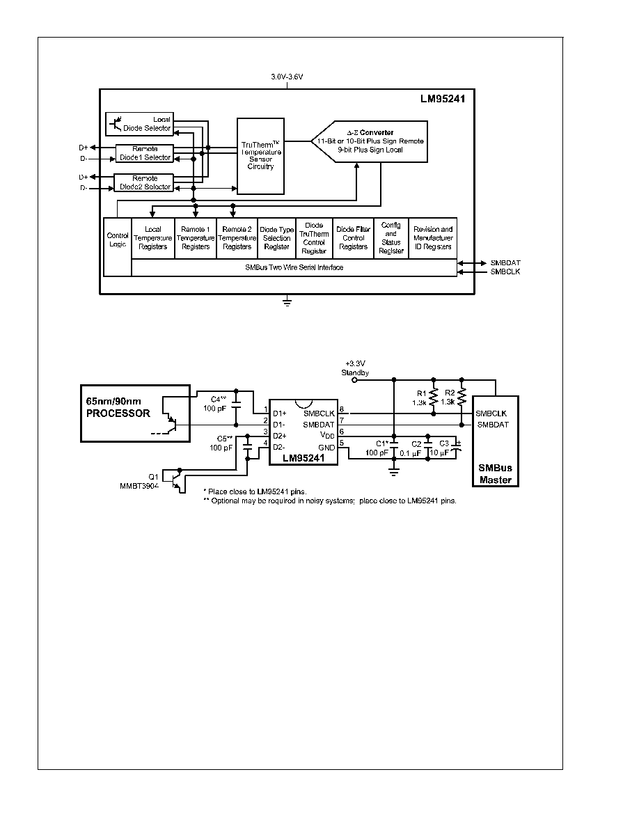
Simplified Block Diagram
20199701
Typical Application
20199703
LM95241
www.national.com
3

Physical Dimensions
inches (millimeters) unless otherwise noted
8-Lead Molded Mini-Small-Outline Package (MSOP),
JEDEC Registration Number MO-187
Order Number LM95241CIMM or LM95241CIMMX
NS Package Number MUA08A
National does not assume any responsibility for use of any circuitry described, no circuit patent licenses are implied and National reserves
the right at any time without notice to change said circuitry and specifications.
For the most current product information visit us at www.national.com.
LIFE SUPPORT POLICY
NATIONAL'S PRODUCTS ARE NOT AUTHORIZED FOR USE AS CRITICAL COMPONENTS IN LIFE SUPPORT DEVICES OR SYSTEMS
WITHOUT THE EXPRESS WRITTEN APPROVAL OF THE PRESIDENT AND GENERAL COUNSEL OF NATIONAL SEMICONDUCTOR
CORPORATION. As used herein:
1. Life support devices or systems are devices or systems
which, (a) are intended for surgical implant into the body, or
(b) support or sustain life, and whose failure to perform when
properly used in accordance with instructions for use
provided in the labeling, can be reasonably expected to result
in a significant injury to the user.
2. A critical component is any component of a life support
device or system whose failure to perform can be reasonably
expected to cause the failure of the life support device or
system, or to affect its safety or effectiveness.
BANNED SUBSTANCE COMPLIANCE
National Semiconductor follows the provisions of the Product Stewardship Guide for Customers (CSP-9-111C2) and Banned Substances
and Materials of Interest Specification (CSP-9-111S2) for regulatory environmental compliance. Details may be found at:
www.national.com/quality/green.
Lead free products are RoHS compliant.
National Semiconductor
Americas Customer
Support Center
Email: new.feedback@nsc.com
Tel: 1-800-272-9959
National Semiconductor
Europe Customer Support Center
Fax: +49 (0) 180-530 85 86
Email: europe.support@nsc.com
Deutsch Tel: +49 (0) 69 9508 6208
English
Tel: +44 (0) 870 24 0 2171
FranÁais Tel: +33 (0) 1 41 91 8790
National Semiconductor
Asia Pacific Customer
Support Center
Email: ap.support@nsc.com
National Semiconductor
Japan Customer Support Center
Fax: 81-3-5639-7507
Email: jpn.feedback@nsc.com
Tel: 81-3-5639-7560
www.national.com
LM95241
Dual
Remote
Diode
T
emperature
Sensor
with
SMBus
Interface
and
T
ruTherm
T
echnology
(65nm/90nm)