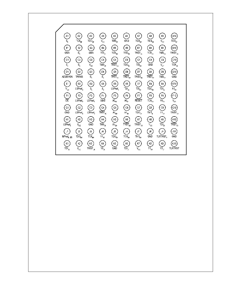
SCANSTA112
7-port Multidrop IEEE 1149.1 (JTAG) Multiplexer
General Description
The SCANSTA112 extends the IEEE Std. 1149.1 test bus
into a multidrop test bus environment. The advantage of a
multidrop approach over a single serial scan chain is im-
proved test throughput and the ability to remove a board
from the system and retain test access to the remaining
modules. Each SCANSTA112 supports up to 7 local
IEEE1149.1 scan chains which can be accessed individually
or combined serially.
Addressing is accomplished by loading the instruction regis-
ter with a value matching that of the Slot inputs. Backplane
and inter-board testing can easily be accomplished by park-
ing the local TAP Controllers in one of the stable TAP Con-
troller states via a Park instruction. The 32-bit TCK counter
enables built in self test operations to be performed on one
port while other scan chains are simultaneously tested.
The STA112 has a unique feature in that the backplane port
and the LSP0 port are bidirectional. They can be configured
to alternatively act as the master or slave port so an alternate
test master can take control of the entire scan chain network
from the LSP0 port while the backplane port becomes a
slave.
Features
n
True IEEE 1149.1 hierarchical and multidrop
addressable capability
n
The 8 slot inputs support up to 249 unique addresses,
an Interrogation Address, Broadcast Address, and 4
Multi-cast Group Addresses (address 000000 is
reserved)
n
7 IEEE 1149.1-compatible configurable local scan ports
n
Bi-directional Backplane and LSP
0
ports are
interchangeable slave ports
n
Capable of ignoring TRST of the backplane port when it
becomes the slave.
n
Stitcher Mode bypasses level 1 and 2 protocols
n
Mode Register
0
allows local TAPs to be bypassed,
selected for insertion into the scan chain individually, or
serially in groups of two or three
n
Transparent Mode can be enabled with a single
instruction to conveniently buffer the backplane IEEE
1149.1 pins to those on a single local scan port
n
General purpose local port passthrough bits are useful
for delivering write pulses for Flash programming or
monitoring device status.
n
Known Power-up state
n
TRST on all local scan ports
n
32-bit TCK counter
n
16-bit LFSR Signature Compactor
n
Local TAPs can become TRI-STATE via the OE input to
allow an alternate test master to take control of the local
TAPs (LSP
0-3
have a TRI-STATE notification output)
n
3.0-3.6V V
CC
Supply Operation
n
Supports live insertion/withdrawal
20051250
FIGURE 1. Typical use of SCANSTA112 for board-level management of multiple scan chains.
February 2003
SCANST
A1
12
7-port
Multidrop
IEEE
1
149.1
(JT
AG)
Multiplexer
� 2003 National Semiconductor Corporation
DS200512
www.national.com

Introduction
The SCANSTA112 is the third device in a series that enable
multi-drop address and multiplexing of IEEE-1149.1 scan
chains. The SCANSTA112 is a superset of its predecessors
- the SCANPSC110 and the SCANSTA111. The STA112 has
all features and functionality of these two previous devices.
The STA112 is essentially a support device for the IEEE
1149.1 standard. It is primarily used to partition scan chains
into managable sizes, or to isolate specific devices onto a
seperate chain (Figure 1). The benefits of multiple scan
chains are improved fault isolation, faster test times, faster
programiing times, and smaller vector sets.
In addition to scan chain partitioning, the device is also
addressable for use in a multidrop backplane environment
(Figure 2). In this configuration, multiple IEEE-1149.1 acces-
sible cards with an STA112 on board can utilize the same
backplane test bus for system-level IEEE-1149.1 access.
This approach facilitates a system-wide commitment to
structural test and programming throughout the entire sys-
tem life sycle.
Architecture
Figure 3 shows the basic architecture of the 'STA112. The
device's major functional blocks are illustrated here.
The TAP Controller, a 16-state state machine, is the central
control for the device. The instruction register and various
test data registers can be scanned to exercise the various
functions of the 'STA112 (these registers behave as defined
in IEEE Std. 1149.1).
The 'STA112 selection controller provides the functionality
that allows the 1149.1 protocol to be used in a multi-drop
environment. It primarily compares the address input to the
slot identification and enables the 'STA112 for subsequent
scan operations.
The Local Scan Port Network (LSPN) contains multiplexing
logic used to select different port configurations. The LSPN
control block contains the Local Scan Port Controllers
(LSPC) for each Local Scan Port (LSP
0
, LSP
1
... LSP
n
). This
control block receives input from the 'STA112 instruction
register, mode registers, and the TAP controller. Each local
port contains all four boundary scan signals needed to inter-
face with the local TAPs plus the optional Test Reset signal
(TRST).
The TDI/TDO Crossover Master/Slave logic is used to define
the bidirectional B0 and B1 ports in a Master/Slave
configuration.
20051251
FIGURE 2. Example of SCANSTA112 in a multidrop addressable backplane.
SCANST
A1
12
www.national.com
2


