TP3054, TP3057
TL H 5510
TP3054
TP3057
``Enhanced''
Serial
Interface
CODECFilter
COMBO
Family
August 1994
TP3054 TP3057
``Enhanced'' Serial Interface
CODEC Filter COMBO
Family
General Description
The TP3054 TP3057 family consists of m-law and A-law
monolithic PCM CODEC filters utilizing the A D and D A
conversion architecture shown in
Figure 1 and a serial PCM
interface The devices are fabricated using National's ad-
vanced double-poly CMOS process (microCMOS)
The encode portion of each device consists of an input gain
adjust amplifier an active RC pre-filter which eliminates very
high frequency noise prior to entering a switched-capacitor
band-pass filter that rejects signals below 200 Hz and above
3400 Hz Also included are auto-zero circuitry and a com-
panding coder which samples the filtered signal and en-
codes it in the companded m-law or A-law PCM format The
decode portion of each device consists of an expanding
decoder which reconstructs the analog signal from the
companded m-law or A-law code a low-pass filter which
corrects for the sin x x response of the decoder output and
rejects signals above 3400 Hz followed by a single-ended
power amplifier capable of driving low impedance loads
The devices require two 1 536 MHz 1 544 MHz or 2 048
MHz transmit and receive master clocks which may be
asynchronous transmit and receive bit clocks which may
vary from 64 kHz to 2 048 MHz and transmit and receive
frame sync pulses The timing of the frame sync pulses and
PCM data is compatible with both industry standard formats
Features
Y
Complete CODEC and filtering system (COMBO)
including
Transmit high-pass and low-pass filtering
Receive low-pass filter with sin x x correction
Active RC noise filters
m
-law or A-law compatible COder and DECoder
Internal precision voltage reference
Serial I O interface
Internal auto-zero circuitry
Y
m
-law 16-pin
TP3054
Y
A-law 16-pin
TP3057
Y
Designed for D3 D4 and CCITT applications
Y
g
5V operation
Y
Low operating power
typically 50 mW
Y
Power-down standby mode
typically 3 mW
Y
Automatic power-down
Y
TTL or CMOS compatible digital interfaces
Y
Maximizes line interface card circuit density
Y
Dual-In-Line or surface mount packages
Y
See also AN-370 ``Techniques for Designing with
CODEC Filter COMBO Circuits''
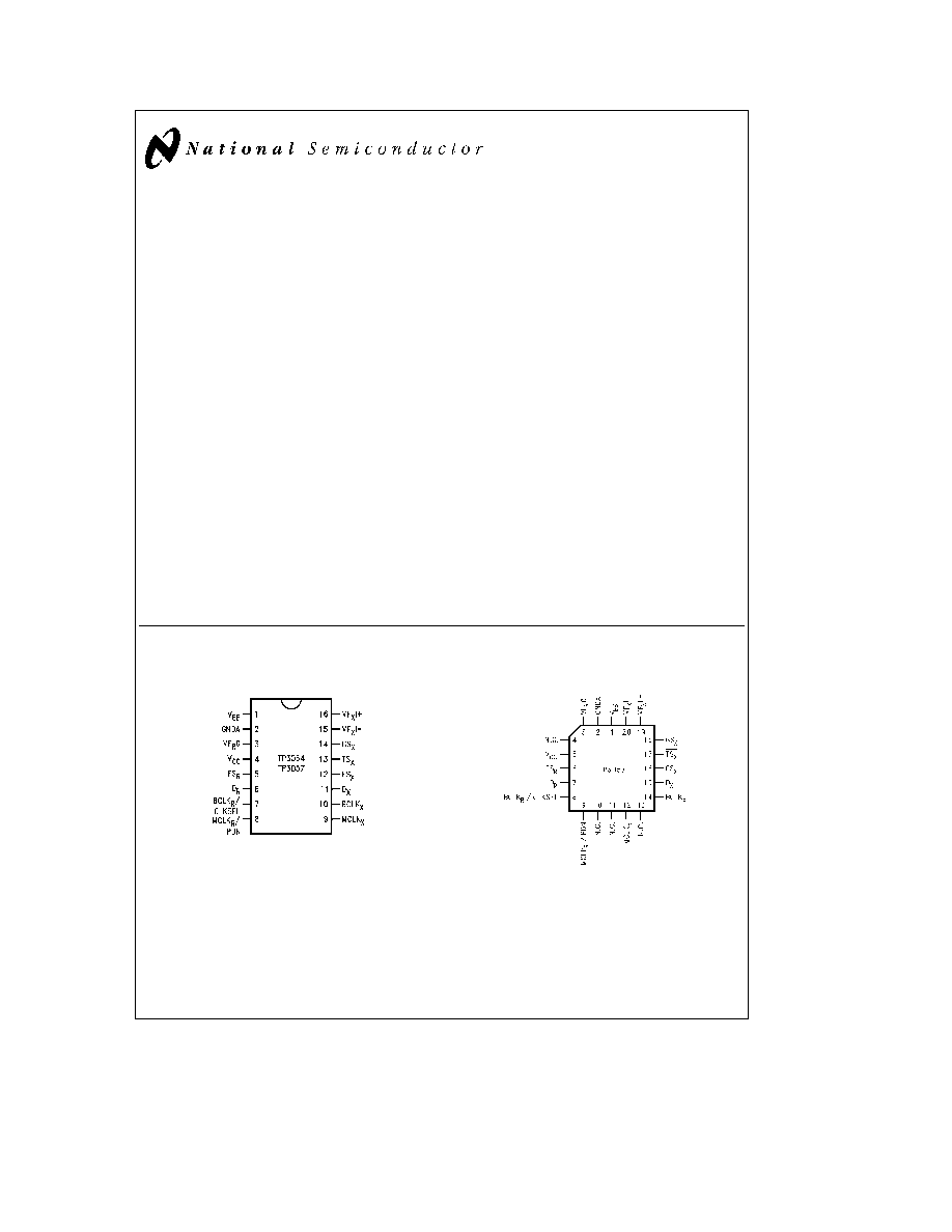
Connection Diagrams
Dual-In-Line Package
TL H 5510 � 1
Top View
Order Number TP3054J or TP3057J
See NS Package Number J16A
Order Number TP3054N or TP3057N
See NS Package Number N16A
Order Number TP3054WM or TP3057WM
See NS Package Number M16B
Plastic Chip Carriers
TL H 5510 � 10
Top View
Order Number TP3057V
See NS Package Number V20A
COMBO
and TRI-STATE
are registered trademarks of National Semiconductor Corporation
C1995 National Semiconductor Corporation
RRD-B30M125 Printed in U S A
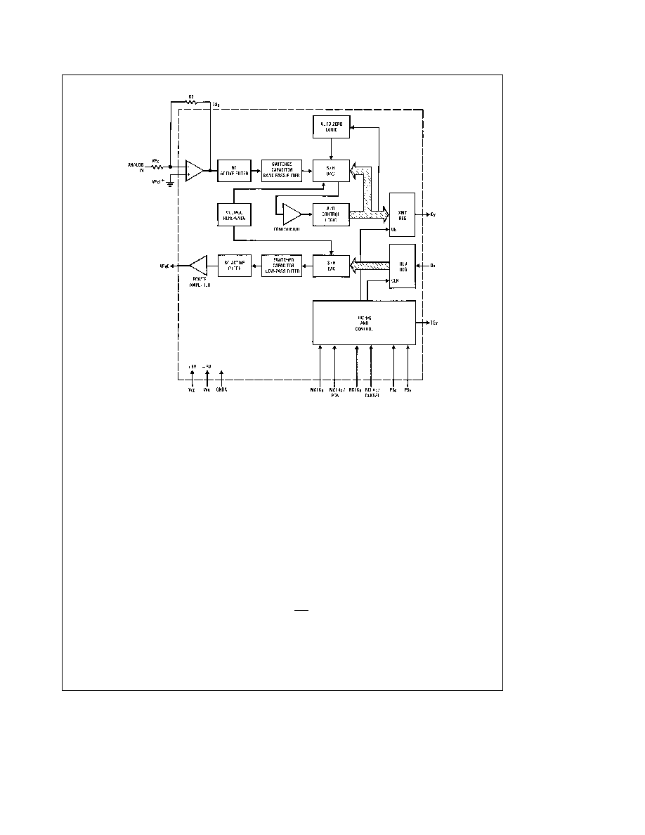
Block Diagram
FIGURE 1
TL H 5510 � 2
Pin Description
Symbol
Function
V
BB
Negative power supply pin
V
BB
e b
5V
g
5%
GNDA
Analog ground All signals are referenced
to this pin
VF
R
O
Analog output of the receive power ampli-
fier
V
CC
Positive power supply pin
V
CC
e a
5V
g
5%
FS
R
Receive frame sync pulse which enables
BCLK
R
to shift PCM data into D
R
FS
R
is
an 8 kHz pulse train See
Figures 2 and 3
for timing details
D
R
Receive data input PCM data is shifted
into D
R
following the FS
R
leading edge
BCLK
R
CLKSEL The bit clock which shifts data into D
R
af-
ter the FS
R
leading edge May vary from
64 kHz to 2 048 MHz Alternatively may
be a logic input which selects either
1 536 MHz 1 544 MHz or 2 048 MHz for
master clock in synchronous mode and
BCLK
X
is used for both transmit and re-
ceive directions (see Table I)
MCLK
R
PDN
Receive
master
clock
Must
be
1 536 MHz 1 544 MHz or 2 048 MHz
May be asynchronous with MCLK
X
but
Symbol
Function
should be synchronous with MCLK
X
for best per-
formance When MCLK
R
is connected continu-
ously low MCLK
X
is selected for all internal tim-
ing When MCLK
R
is connected continuously
high the device is powered down
MCLK
X
Transmit master clock Must be 1 536 MHz
1 544 MHz or 2 048 MHz May be asynchronous
with MCLK
R
Best performance is realized from
synchronous operation
FS
X
Transmit frame sync pulse input which enables
BCLK
X
to shift out the PCM data on D
X
FS
X
is
an 8 kHz pulse train see
Figures 2 and 3 for
timing details
BCLK
X
The bit clock which shifts out the PCM data on
D
X
May vary from 64 kHz to 2 048 MHz but
must be synchronous with MCLK
X
D
X
The TRI-STATE
PCM data output which is en-
abled by FS
X
TS
X
Open drain output which pulses low during the
encoder time slot
GS
X
Analog output of the transmit input amplifier
Used to externally set gain
VF
X
I
b
Inverting input of the transmit input amplifier
VF
X
I
a
Non-inverting input of the transmit input amplifi-
er
2
Functional Description
POWER-UP
When power is first applied power-on reset circuitry initializ-
es the COMBO and places it into a power-down state All
non-essential circuits are deactivated and the D
X
and VF
R
O
outputs are put in high impedance states To power-up the
device a logical low level or clock must be applied to the
MCLK
R
PDN pin
and FS
X
and or FS
R
pulses must be pres-
ent Thus 2 power-down control modes are available The
first is to pull the MCLK
R
PDN pin high the alternative is to
hold both FS
X
and FS
R
inputs continuously low
the device
will power-down approximately 1 ms after the last FS
X
or
FS
R
pulse Power-up will occur on the first FS
X
or FS
R
pulse The TRI-STATE PCM data output D
X
will remain in
the high impedance state until the second FS
X
pulse
SYNCHRONOUS OPERATION
For synchronous operation the same master clock and bit
clock should be used for both the transmit and receive di-
rections In this mode a clock must be applied to MCLK
X
and the MCLK
R
PDN pin can be used as a power-down
control A low level on MCLK
R
PDN powers up the device
and a high level powers down the device In either case
MCLK
X
will be selected as the master clock for both the
transmit and receive circuits A bit clock must also be ap-
plied to BCLK
X
and the BCLK
R
CLKSEL can be used to
select the proper internal divider for a master clock of 1 536
MHz 1 544 MHz or 2 048 MHz For 1 544 MHz operation
the device automatically compensates for the 193rd clock
pulse each frame
With a fixed level on the BCLK
R
CLKSEL pin BCLK
X
will be
selected as the bit clock for both the transmit and receive
directions Table 1 indicates the frequencies of operation
which can be selected depending on the state of BCLK
R
CLKSEL In this synchronous mode the bit clock BCLK
X
may be from 64 kHz to 2 048 MHz but must be synchro-
nous with MCLK
X
Each FS
X
pulse begins the encoding cycle and the PCM
data from the previous encode cycle is shifted out of the
enabled D
X
output on the positive edge of BCLK
X
After 8
bit clock periods the TRI-STATE D
X
output is returned to a
high impedance state With an FS
R
pulse PCM data is
latched via the D
R
input on the negative edge of BCLK
X
(or
BCLK
R
if running) FS
X
and FS
R
must be synchronous with
MCLK
X R
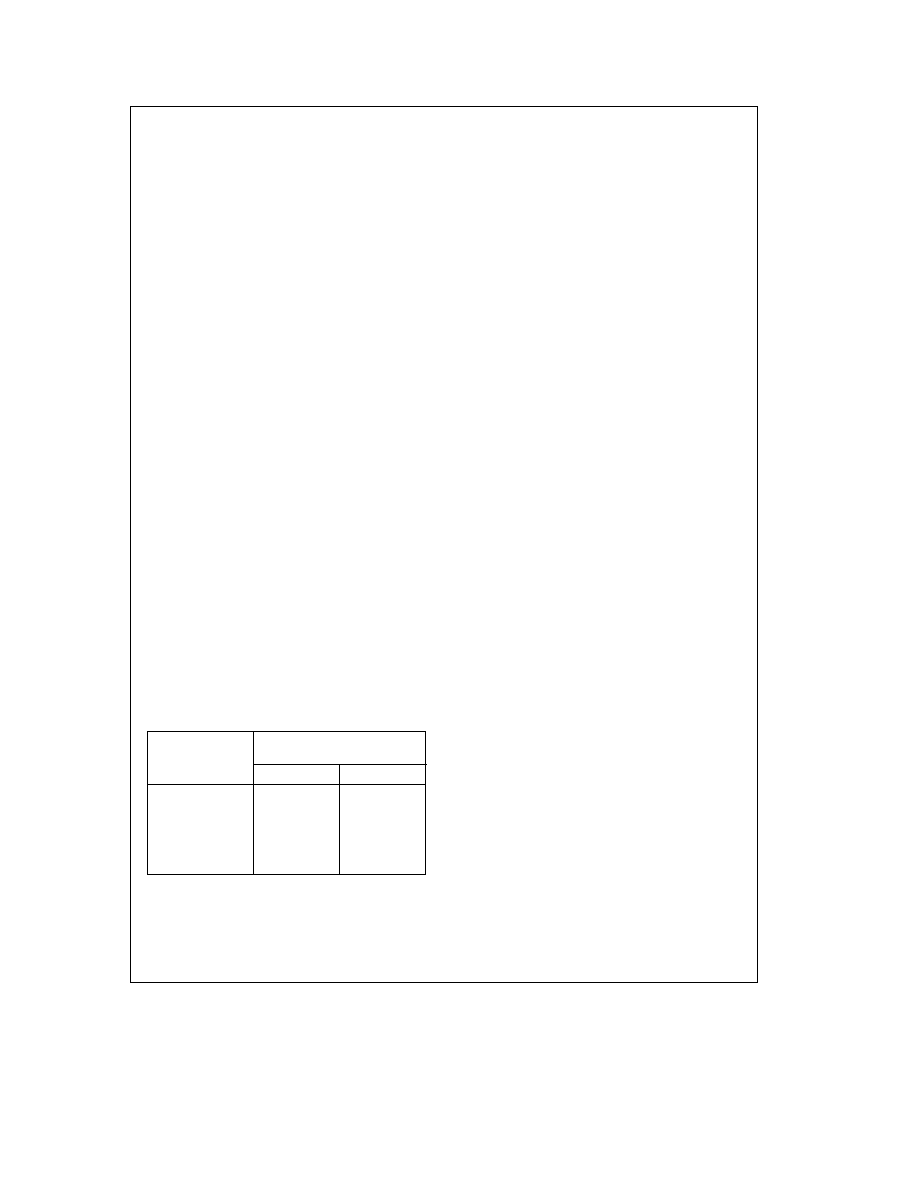
TABLE I Selection of Master Clock Frequencies
BCLK
R
CLKSEL
Master Clock
Frequency Selected
TP3057
TP3054
Clocked
2 048 MHz
1 536 MHz or
1 544 MHz
0
1 536 MHz or
2 048 MHz
1 544 MHz
1
2 048 MHz
1 536 MHz or
1 544 MHz
ASYNCHRONOUS OPERATION
For asynchronous operation separate transmit and receive
clocks may be applied
MCLK
X
and MCLK
R
must be
2 048 MHz for the TP3057 or 1 536 MHz 1 544 MHz for the
TP3054 and need not be synchronous For best transmis-
sion performance however MCLK
R
should be synchronous
with MCLK
X
which is easily achieved by applying only static
logic levels to the MCLK
R
PDN pin This will automatically
connect MCLK
X
to all internal MCLK
R
functions (see Pin
Description) For 1 544 MHz operation the device automati-
cally compensates for the 193rd clock pulse each frame
FS
X
starts each encoding cycle and must be synchronous
with MCLK
X
and BCLK
X
FS
R
starts each decoding cycle
and must be synchronous with BCLK
R
BCLK
R
must be a
clock the logic levels shown in Table 1 are not valid in
asynchronous mode BCLK
X
and BCLK
R
may operate from
64 kHz to 2 048 MHz
SHORT FRAME SYNC OPERATION
The COMBO can utilize either a short frame sync pulse or a
long frame sync pulse Upon power initialization the device
assumes a short frame mode In this mode both frame sync
pulses FS
X
and FS
R
must be one bit clock period long
with timing relationships specified in
Figure 2 With FS
X
high
during a falling edge of BCLK
X
the next rising edge of
BCLK
X
enables the D
X
TRI-STATE output buffer which will
output the sign bit The following seven rising edges clock
out the remaining seven bits and the next falling edge dis-
ables the D
X
output With FS
R
high during a falling edge of
BCLK
R
(BCLK
X
in synchronous mode) the next falling edge
of BCLK
R
latches in the sign bit The following seven falling
edges latch in the seven remaining bits All four devices
may utilize the short frame sync pulse in synchronous or
asynchronous operating mode
LONG FRAME SYNC OPERATION
To use the long frame mode both the frame sync pulses
FS
X
and FS
R
must be three or more bit clock periods long
with timing relationships specified in
Figure 3 Based on the
transmit frame sync FS
X
the COMBO will sense whether
short or long frame sync pulses are being used For 64 kHz
operation the frame sync pulse must be kept low for a mini-
mum of 160 ns The D
X
TRI-STATE output buffer is enabled
with the rising edge of FS
X
or the rising edge of BCLK
X
whichever comes later and the first bit clocked out is the
sign bit The following seven BCLK
X
rising edges clock out
the remaining seven bits The D
X
output is disabled by the
falling BCLK
X
edge following the eighth rising edge or by
FS
X
going low whichever comes later A rising edge on the
receive frame sync pulse FS
R
will cause the PCM data at
D
R
to be latched in on the next eight falling edges of BCLK
R
(BCLK
X
in synchronous mode) All four devices may utilize
the long frame sync pulse in synchronous or asynchronous
mode
In applications where the LSB bit is used for signalling with
FS
R
two bit clock periods long the decoder will interpret the
lost LSB as ``
'' to minimize noise and distortion
3

Functional Description
(Continued)
TRANSMIT SECTION
The transmit section input is an operational amplifier with
provision for gain adjustment using two external resistors
see
Figure 4 The low noise and wide bandwidth allow gains
in excess of 20 dB across the audio passband to be real-
ized The op amp drives a unity-gain filter consisting of RC
active pre-filter followed by an eighth order switched-ca-
pacitor bandpass filter clocked at 256 kHz The output of
this filter directly drives the encoder sample-and-hold circuit
The A D is of companding type according to m-law
(TP3054) or A-law (TP3057) coding conventions A preci-
sion voltage reference is trimmed in manufacturing to pro-
vide an input overload (t
MAX
) of nominally 2 5V peak (see
table of Transmission Characteristics) The FS
X
frame sync
pulse controls the sampling of the filter output and then the
successive-approximation encoding cycle begins The 8-bit
code is then loaded into a buffer and shifted out through D
X
at the next FS
X
pulse The total encoding delay will be ap-
proximately 165 ms (due to the transmit filter) plus 125 ms
(due to encoding delay) which totals 290 ms Any offset
voltage due to the filters or comparator is cancelled by sign
bit integration
RECEIVE SECTION
The receive section consists of an expanding DAC which
drives a fifth order switched-capacitor low pass filter
clocked at 256 kHz The decoder is A-law (TP3057) or
m
-law (TP3054) and the 5th order low pass filter corrects for
the sin x x attenuation due to the 8 kHz sample hold The
filter is then followed by a 2nd order RC active post-filter
power amplifer capable of driving a 600X load to a level of
7 2 dBm The receive section is unity-gain Upon the occur-
rence of FS
R
the data at the D
R
input is clocked in on the
falling edge of the next eight BCLK
R
(BCLK
X
) periods At
the end of the decoder time slot the decoding cycle begins
and 10 ms later the decoder DAC output is updated The
total decoder delay is E 10 ms (decoder update) plus
110 ms (filter delay) plus 62 5 ms (
frame) which gives
approximately 180 ms
4
Absolute Maximum Ratings
If Military Aerospace specified devices are required
please contact the National Semiconductor Sales
Office Distributors for availability and specifications
V
CC
to GNDA
7V
V
BB
to GNDA
b
7V
Voltage at any Analog Input
or Output
V
CC
a
0 3V to V
BB
b
0 3V
Voltage at any Digital Input or
Output
V
CC
a
0 3V to GNDA
b
0 3V
Operating Temperature Range
b
25 C to
a
125 C
Storage Temperature Range
b
65 C to
a
150 C
Lead Temperature (Soldering 10 seconds)
300 C
ESD (Human Body Model)
2000V
Latch-Up Immunity
e
100 mA on any Pin
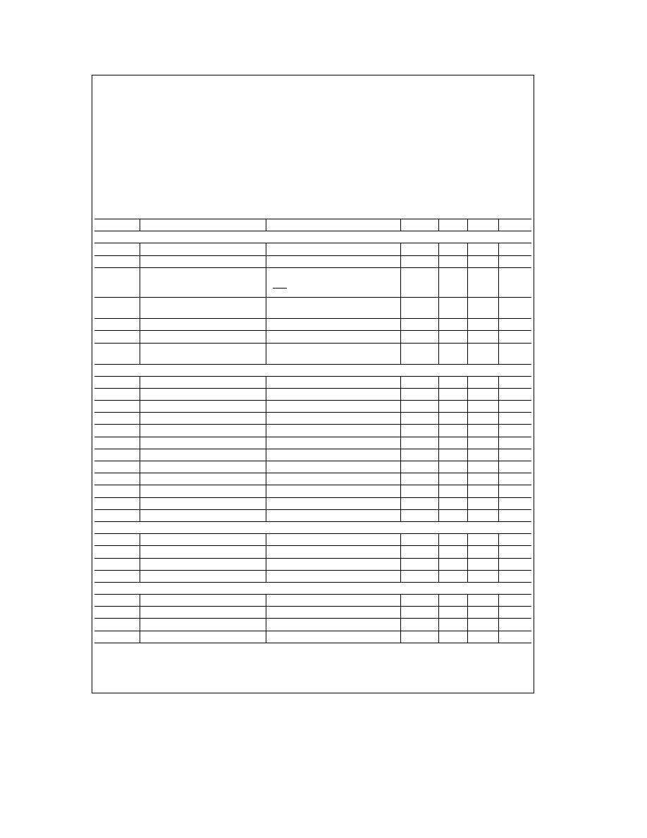
Electrical Characteristics
Unless otherwise noted limits printed in BOLD characters are guaranteed for V
CC
e
5 0V
g
5% V
BB
e b
5 0V
g
5% T
A
e
0 C to 70 C by correlation with 100% electrical testing at T
A
e
25 C All other limits
are assured by correlation with other production tests and or product design and characterization All signals referenced to
GNDA Typicals specified at V
CC
e
5 0V V
BB
e b
5 0V T
A
e
25 C
Symbol
Parameter
Conditions
Min
Typ
Max
Units
DIGITAL INTERFACE
V
IL
Input Low Voltage
0 6
V
V
IH
Input High Voltage
2 2
V
V
OL
Output Low Voltage
D
X
I
L
e
3 2 mA
0 4
V
SIG
R
I
L
e
1 0 mA
0 4
V
TS
X
I
L
e
3 2 mA Open Drain
0 4
V
V
OH
Output High Voltage
D
X
I
H
e b
3 2 mA
2 4
V
SIG
R
I
H
e b
1 0 mA
2 4
V
I
IL
Input Low Current
GNDA
s
V
IN
s
V
IL
All Digital Inputs
b
10
10
m
A
I
IH
Input High Current
V
IH
s
V
IN
s
V
CC
b
10
10
m
A
I
OZ
Output Current in High Impedance
D
X
GNDA
s
V
O
s
V
CC
b
10
10
m
A
State (TRI-STATE)
ANALOG INTERFACE WITH TRANSMIT INPUT AMPLIFIER (ALL DEVICES)
I
I
XA
Input Leakage Current
b
2 5V
s
V
s
a
2 5V VF
X
I
a
or VF
X
I
b
b
200
200
nA
R
I
XA
Input Resistance
b
2 5V
s
V
s
a
2 5V VF
X
I
a
or VF
X
I
b
10
MX
R
O
XA
Output Resistance
Closed Loop Unity Gain
1
3
X
R
L
XA
Load Resistance
GS
X
10
kX
C
L
XA
Load Capacitance
GS
X
50
pF
V
O
XA
Output Dynamic Range
GS
X
R
L
t
10 kX
b
2 8
2 8
V
A
V
XA
Voltage Gain
VF
X
I
a
to GS
X
5000
V V
F
U
XA
Unity Gain Bandwidth
1
2
MHz
V
OS
XA
Offset Voltage
b
20
20
mV
V
CM
XA
Common-Mode Voltage
CMRRXA
l
60 dB
b
2 5
2 5
V
CMRRXA
Common-Mode Rejection Ratio
DC Test
60
dB
PSRRXA
Power Supply Rejection Ratio
DC Test
60
dB
ANALOG INTERFACE WITH RECEIVE FILTER (ALL DEVICES)
R
O
RF
Output Resistance
Pin VF
R
O
1
3
X
R
L
RF
Load Resistance
VF
R
O
e
g
2 5V
600
X
C
L
RF
Load Capacitance
500
pF
VOS
R
O
Output DC Offset Voltage
b
200
200
mV
POWER DISSIPATION (ALL DEVICES)
I
CC
0
Power-Down Current
No Load (Note)
0 5
1 5
mA
I
BB
0
Power-Down Current
No Load (Note)
0 05
0 3
mA
I
CC
1
Power-Up Active Current
No Load
5 0
9 0
mA
I
BB
1
Power-Up Active Current
No Load
5 0
9 0
mA
Note
I
CC0
and I
BB0
are measured after first achieving a power-up state
5