
NTE1214
Integrated Circuit
AM Tuner System
Description:
The NTE1214 is a high integrated circuit in a 16≠Lead DIP type package designed for use in the AM
system of high grade receivers. This device contains most of the functions needed for AM receiving.
Functions:
D
RF Amplifier
D
Frequency Counter
D
IF Amplifier
D
Detector
D
AGC
D
Signal Meter Driving
Features:
D
RF Amplifier Stage:
Good quieting sensitivity by means of low noise transistors and cascade connecting.
D
Frequency Converter Stage:
Splendid spurious characteristics by means of reduction of high frequency distortion in local
oscillation and differential mixer.
D
IF Amplifier Stage:
Reasonable distortion by wide output dynamic range.
D
Detector Stage:
Low distortion even at deep modulation considering diagonal clip or negative clip.
D
AGC Stage:
Wide AGC range and good large input signal characteristics by AGC'd IF and RF amplifier
stage.
D
Signal Meter Driving Stage:
Excellent linearity to input signal.
D
Others:
Stabilized biasing against supply voltage drifting over all stages. Particularly superior com-
pensation circuit in IF amplifier. Less deterioration of gain, detector output, and distortion in
low supply voltage range in order to get wide supply voltage range (7V* to 16V).
*
Needs to vary peripheral parts and its value of RF and local oscillator stage for the purpose of low
supply voltage operation.
Absolute Maximum Ratings: (T
A
= +25
∞
C unless otherwise specified)
Maximum Supply Voltage (Pin3, Pin11), V
CC
max
16V
. . . . . . . . . . . . . . . . . . . . . . . . . . . . . . . . . . . . . . .
Output Voltage (Pin4, Pin5), v
o
24V
. . . . . . . . . . . . . . . . . . . . . . . . . . . . . . . . . . . . . . . . . . . . . . . . . . . . . . .
Input Voltage (Pin2), v
i
0 to 4V
. . . . . . . . . . . . . . . . . . . . . . . . . . . . . . . . . . . . . . . . . . . . . . . . . . . . . . . . . . .
Supply Current (Pin3, Pin4, Pin5, Pin11), I
CC
30mA
. . . . . . . . . . . . . . . . . . . . . . . . . . . . . . . . . . . . . . . .
Flow≠Out Current (Pin15), I
15
2mA
. . . . . . . . . . . . . . . . . . . . . . . . . . . . . . . . . . . . . . . . . . . . . . . . . . . . . . .
Allowable Power Dissipation (T
A
+70
∞
C), P
D
max
450mW
. . . . . . . . . . . . . . . . . . . . . . . . . . . . . . . . . .
Operating Temperature Range, T
opr
≠20
∞
to +70
∞
C
. . . . . . . . . . . . . . . . . . . . . . . . . . . . . . . . . . . . . . . . .
Storage Temperature Range, T
stg
≠40
∞
to +125
∞
C
. . . . . . . . . . . . . . . . . . . . . . . . . . . . . . . . . . . . . . . . . .
Recommended Operating Conditions: (T
A
= +25
∞
C unless otherwise specified)
Recommended Supply Voltage, V
CC
12V
. . . . . . . . . . . . . . . . . . . . . . . . . . . . . . . . . . . . . . . . . . . . . . . . . .
Electrical Characteristics: (T
A
= +25
∞
C, V
CC
= 12V, f = 1000kHz, f
m
= 400Hz unless otherwise
specified)
Parameter
Symbol
Test Conditions
Min
Typ
Max
Unit
Current Dissipation
I
CC
No Input
≠
16
23
mA
Detector Output
v
o
Input 23dB, 30% MOD
≠27.5
≠23.0
≠
dBm
Input 80dB, 30% MOD
≠16
≠13
≠10
dBm
Signal≠to≠Noise Ratio
S/N
Input 23dB, 30% MOD
16
20
≠
dB
Input 80dB, 30% MOD
49
53
≠
dB
Total Harmonic Distortion
THD
Input 80dB, 80% MOD
≠
0.5
1.0
%
Input 107dB, 30% MOD
≠
0.3
1.0
%
Signal Meter Driving Output
V
SM
Input 107dB, 30% MOD
0.40
0.44
0.48
V
Note 1. 0dBm is defined as 0.775V, and in IF circuit 0dB is 1
µ
V of IHF input at the use of IHF dummy
antenna.
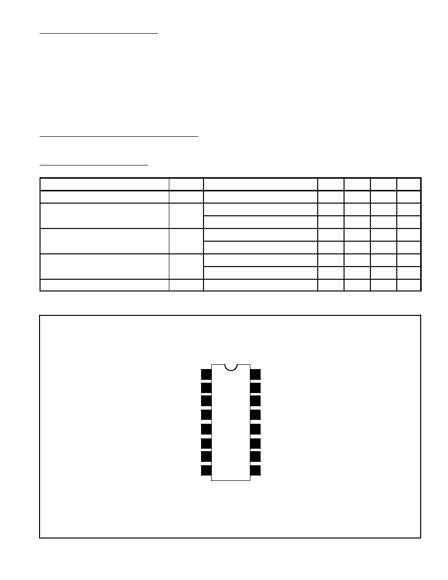
IF System V
CC
2
nd
IF Amp Output
3
rd
IF Amp Input Tune
3
rd
IF Amp Input
Pin Connection Diagram
Converter V
CC
OSC Tank Circuit
Converter Output
DC Return (Substrate)
Detector Output
AGC Bypass
RF Amp DC Bypass
Converter Input
RF Amp Output
RF Tune
RF Amp DC Bypass
1
2
3
4
5
6
7
8
16
15
14
13
Tune Meter Output
12
11
10
9
