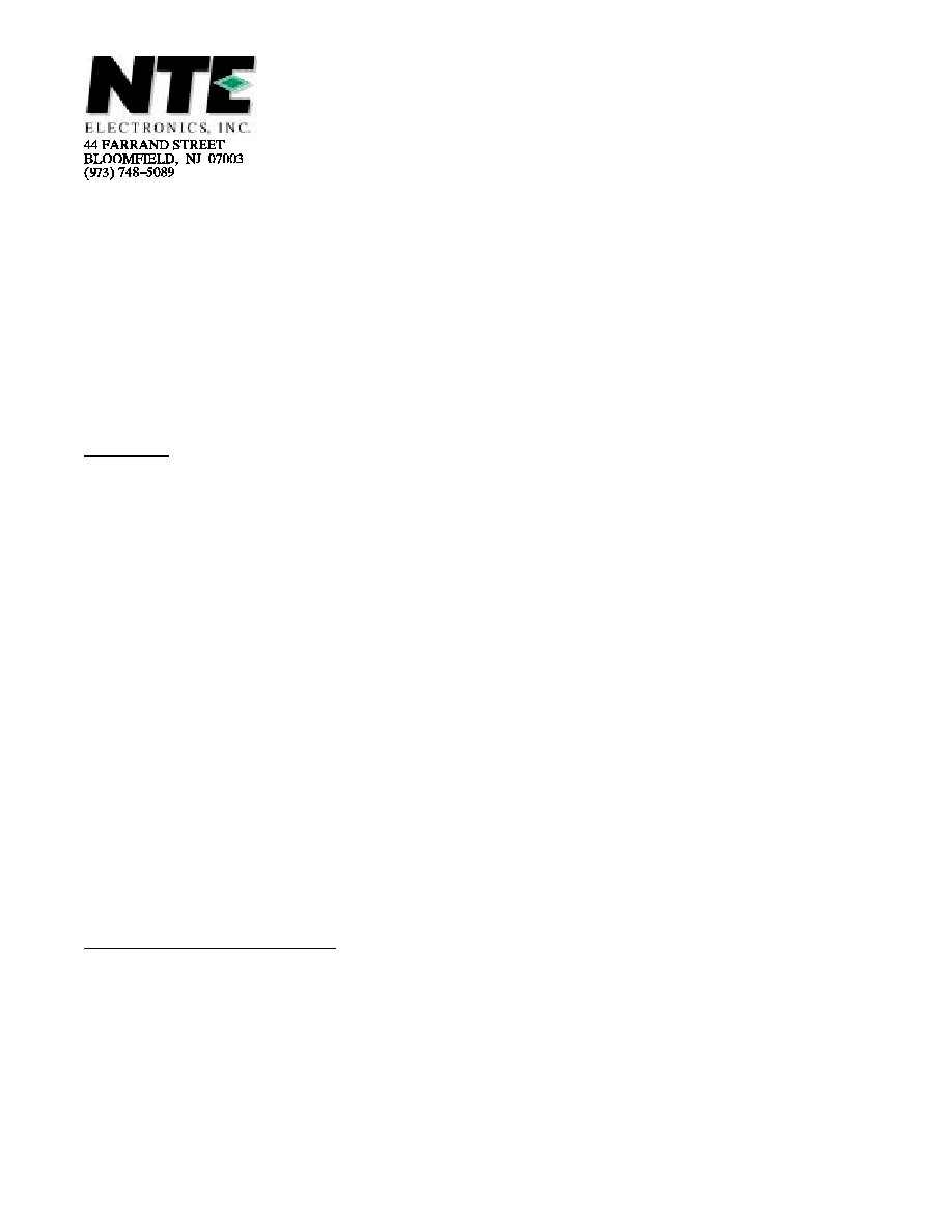
NTE1254
Integrated Circuit
Phase≠Lock Loop (PLL) Frequency
Synthesizer for CB
Features:
D
Programmable Divider ≠ Divided by 3 to 255
D
10≠Bit Divider
D
Phase Detector
D
Reference Oscillation Circuit
D
On≠Chip Filter Amplifier
D
Code Converter
D
Only two or three crystals required for CB radio AM frequency selection
D
Unlocked signals are detected at instant stop "IS" terminal
D
Two type program mode can be selected to change input mode level
M: Low level
Binary code input enables, divided by 3 to 255
.
M: High level
BCD code enables that the data at P
1
to P
6
port is offset 90 by code converter
.
D
Internal active filter amplifier has a long holding time due to very high input impedance charac-
teristics of the CMOS≠this is to obtain very good spurious response.
D
Output signal of the "I" can be used to stop the spurious radiation when the channel selector
makes misprogramming such as rotary switch's lose contact.
D
High speed and low power consumption due to CMOS
D
Single power supply and fully TTL compatible: V
DD
= 5
±
0.5 Volts
D
Operating Temperature: T
A
= ≠30
∞
to 65
∞
C
D
Pull down resistors installed in program and mode switch inputs
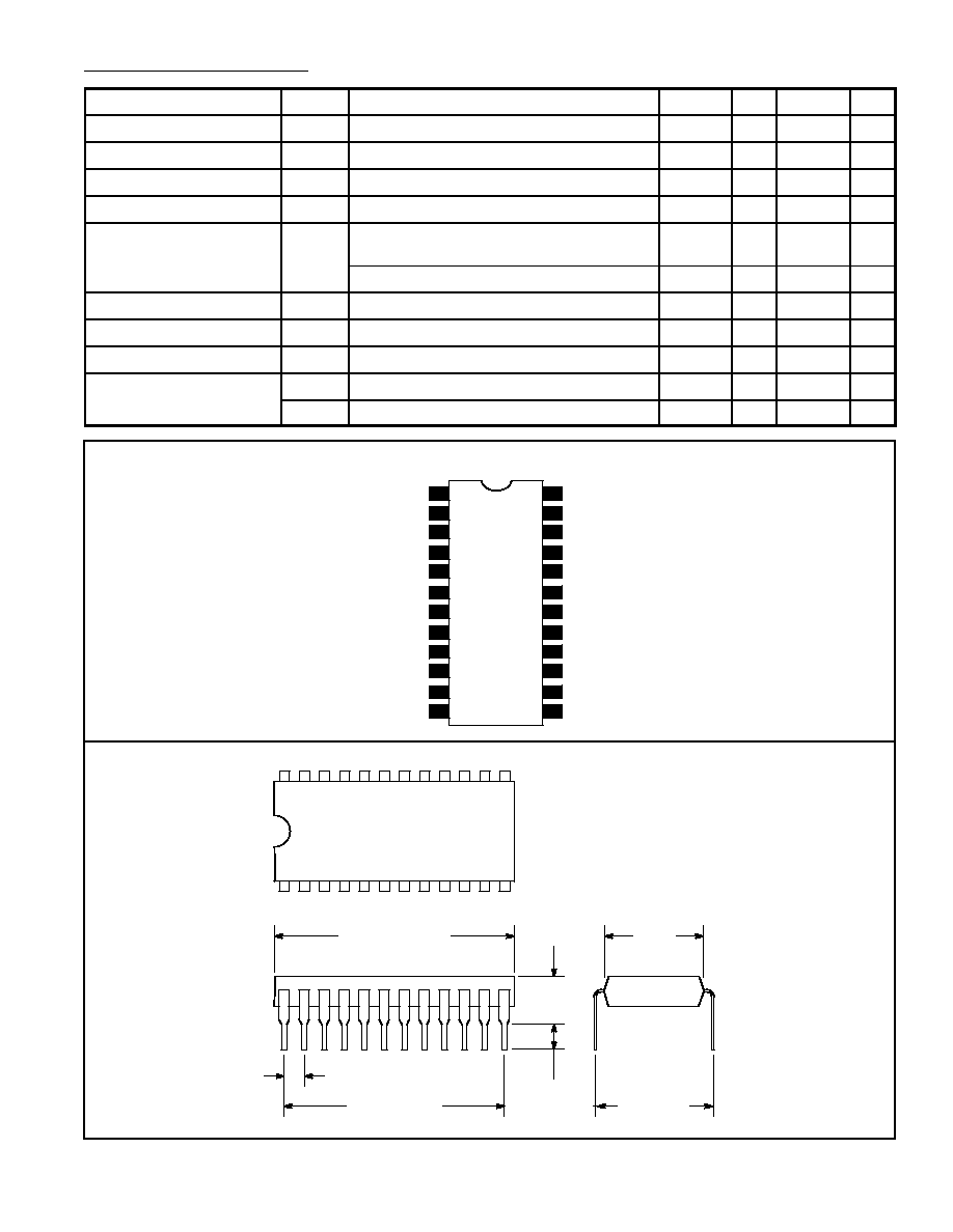
Absolute Maximum Ratings:
Supply Voltage
≠0.3 to +6.0V
. . . . . . . . . . . . . . . . . . . . . . . . . . . . . . . . . . . . . . . . . . . . . . . . . . . . . . . . . . . .
Input Voltage
≠0.3 to +6.0V
. . . . . . . . . . . . . . . . . . . . . . . . . . . . . . . . . . . . . . . . . . . . . . . . . . . . . . . . . . . . .
Operating Temperature Range, T
opr
≠35
∞
to +75
∞
C
. . . . . . . . . . . . . . . . . . . . . . . . . . . . . . . . . . . . . . . . .
Storage Temperature Range, T
stg
≠55
∞
to +125
∞
C
. . . . . . . . . . . . . . . . . . . . . . . . . . . . . . . . . . . . . . . . . .