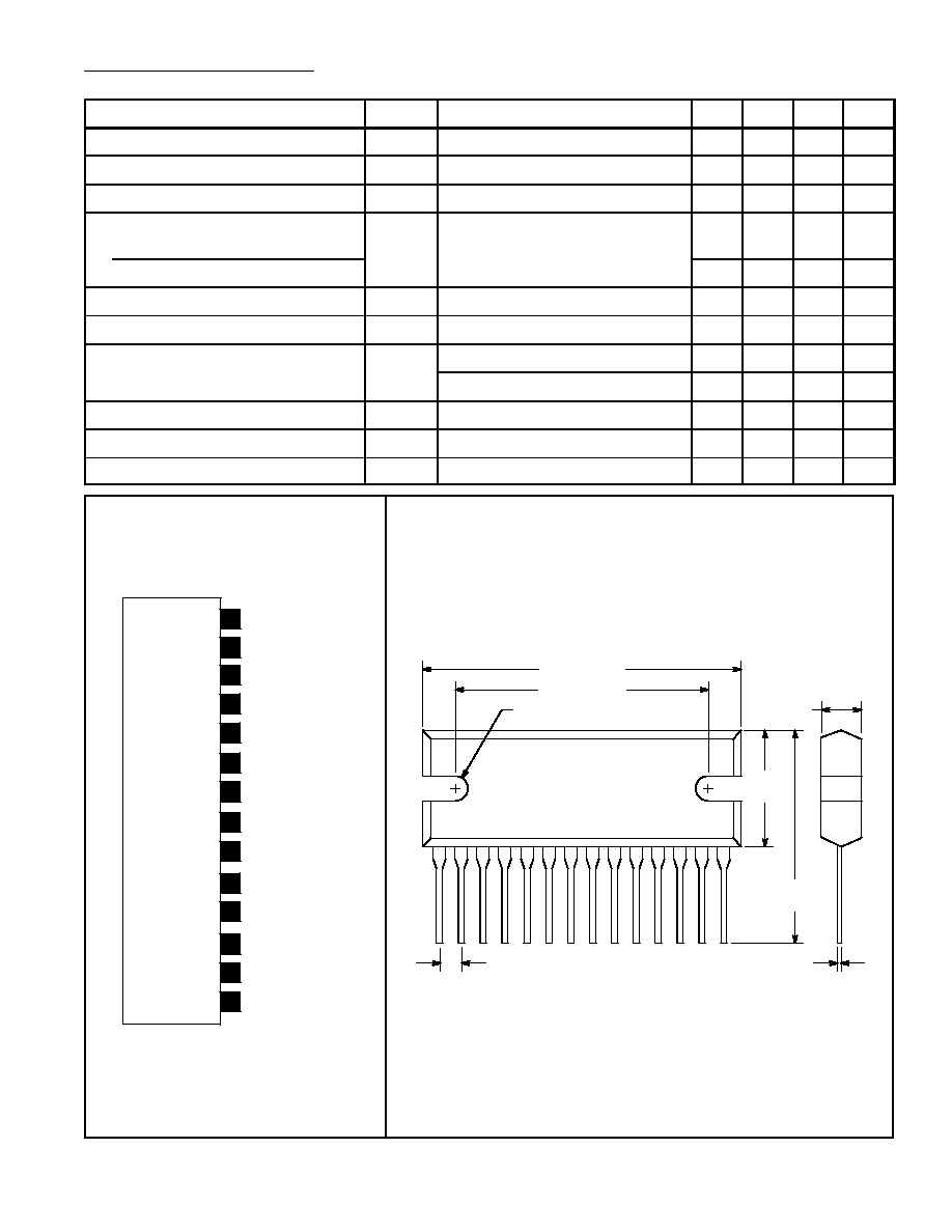
NTE1377
Integrated Circuit
AF Power Amplifier, 6W/Channel
Features:
D
Built≠In 2 Channels (Dual) Enabling use in Stereo and Bridge Amplifier Applications
Dual: 6W x 2 Typ
Bridge: 19W Typ
D
Minimum Number of External Parts Required
D
Low Pop Noise during Power Supply ON/OFF and Good Starting Balance
D
Good Ripple Rejection: 46dB Typ
D
Good Channel Separation
D
Low Residual Noise (R
g
= 0)
D
Low Distortion over a Wide Range of Low to High Frequencies
D
Built≠In Audio Muting Function
D
Built≠In Protectors:
a. Thermal Protection
b. Overvoltage, Surge Voltage Protection
c. Pin≠to≠Pin Short Protection
Absolute Maximum Ratings: (T
A
= +25
∞
C unless otherwise specified)
Maximum Supply Voltage, V
CC
max
Quiescent (t = 30sec)
25V
. . . . . . . . . . . . . . . . . . . . . . . . . . . . . . . . . . . . . . . . . . . . . . . . . . . . . . . . .
Operating
18V
. . . . . . . . . . . . . . . . . . . . . . . . . . . . . . . . . . . . . . . . . . . . . . . . . . . . . . . . . . . . . . . . . . .
Surge Supply Voltage (t
0.2sec), V
CC
surge
50V
. . . . . . . . . . . . . . . . . . . . . . . . . . . . . . . . . . . . . . . . . .
Allowable Power Dissipation (T
C
= +75
∞
C), P
d
max
15W
. . . . . . . . . . . . . . . . . . . . . . . . . . . . . . . . . . . . .
Thermal Resistance, Junction to Case, R
JC
3
∞
C/W
. . . . . . . . . . . . . . . . . . . . . . . . . . . . . . . . . . . . . . . . .
Operating Temperature Range, T
opr
≠20
∞
to +75
∞
C
. . . . . . . . . . . . . . . . . . . . . . . . . . . . . . . . . . . . . . . . .
Storage Temperature Range, T
stg
≠40
∞
to +150
∞
C
. . . . . . . . . . . . . . . . . . . . . . . . . . . . . . . . . . . . . . . . . .
Recommended Operating Conditions: (T
A
= +25
∞
C unless otherwise specified)
Recommended Supply Voltage, V
CC
13.2V
. . . . . . . . . . . . . . . . . . . . . . . . . . . . . . . . . . . . . . . . . . . . . . . .
Load Resistance, R
L
Dual
2
to 8
. . . . . . . . . . . . . . . . . . . . . . . . . . . . . . . . . . . . . . . . . . . . . . . . . . . . . . . . . . . . . . . . . . .
Bridge
4
to 8
. . . . . . . . . . . . . . . . . . . . . . . . . . . . . . . . . . . . . . . . . . . . . . . . . . . . . . . . . . . . . . . . .