NTE5400 thru NTE5406
Silicon Controlled Rectifier (SCR)
0.8 Amp Sensitive Gate
Description:
The NTE5400 through NTE5406 sensitive gate SCR semiconductors are halfwave unidirectional
gate controlled rectifiers (SCR≠thyristor) rated at 0.8 amps RMS maximum on≠state current, with
rated voltages up to 600 volts.
These devices feature 200 microamp gate sensitivity, 5 millamp holding current and 8 amp surge ca-
pabilities.
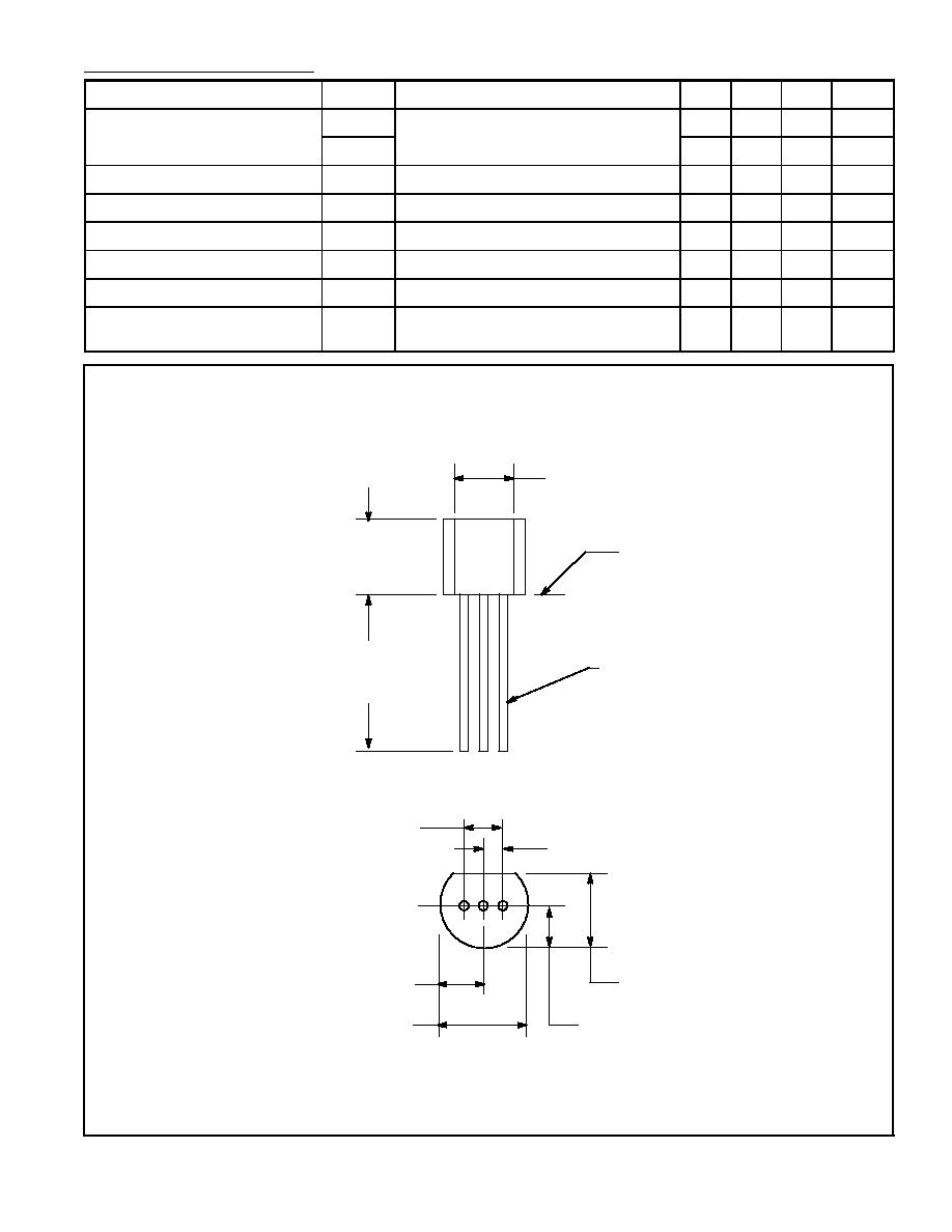
Available in a TO≠92 plastic package, these devices feature excellent environmental stress and tem-
perature cycling characteristics and, coupled with their small size and electrical performance, lend
themselves to various types of control functions encountered with sensors, motors, lamps, relays,
counters, triggers, etc.
Absolute Maximum Ratings:
Repetitive Peak Reverse Voltage (T
C
= +100
∞
C), V
RRM
NTE5400
30V
. . . . . . . . . . . . . . . . . . . . . . . . . . . . . . . . . . . . . . . . . . . . . . . . . . . . . . . . . . . . . . . . . . . .
NTE5401
60V
. . . . . . . . . . . . . . . . . . . . . . . . . . . . . . . . . . . . . . . . . . . . . . . . . . . . . . . . . . . . . . . . . . . .
NTE5402
100V
. . . . . . . . . . . . . . . . . . . . . . . . . . . . . . . . . . . . . . . . . . . . . . . . . . . . . . . . . . . . . . . . . . .
NTE5403
150V
. . . . . . . . . . . . . . . . . . . . . . . . . . . . . . . . . . . . . . . . . . . . . . . . . . . . . . . . . . . . . . . . . . .
NTE5404
200V
. . . . . . . . . . . . . . . . . . . . . . . . . . . . . . . . . . . . . . . . . . . . . . . . . . . . . . . . . . . . . . . . . . .
NTE5405
400V
. . . . . . . . . . . . . . . . . . . . . . . . . . . . . . . . . . . . . . . . . . . . . . . . . . . . . . . . . . . . . . . . . . .
NTE5406
600V
. . . . . . . . . . . . . . . . . . . . . . . . . . . . . . . . . . . . . . . . . . . . . . . . . . . . . . . . . . . . . . . . . . .
Repetitive Peak Off≠State Voltage (T
C
= +100
∞
C), V
DRXM
NTE5400
30V
. . . . . . . . . . . . . . . . . . . . . . . . . . . . . . . . . . . . . . . . . . . . . . . . . . . . . . . . . . . . . . . . . . . .
NTE5401
60V
. . . . . . . . . . . . . . . . . . . . . . . . . . . . . . . . . . . . . . . . . . . . . . . . . . . . . . . . . . . . . . . . . . . .
NTE5402
100V
. . . . . . . . . . . . . . . . . . . . . . . . . . . . . . . . . . . . . . . . . . . . . . . . . . . . . . . . . . . . . . . . . . .
NTE5403
150V
. . . . . . . . . . . . . . . . . . . . . . . . . . . . . . . . . . . . . . . . . . . . . . . . . . . . . . . . . . . . . . . . . . .
NTE5404
200V
. . . . . . . . . . . . . . . . . . . . . . . . . . . . . . . . . . . . . . . . . . . . . . . . . . . . . . . . . . . . . . . . . . .
NTE5405
400V
. . . . . . . . . . . . . . . . . . . . . . . . . . . . . . . . . . . . . . . . . . . . . . . . . . . . . . . . . . . . . . . . . . .
NTE5406
600V
. . . . . . . . . . . . . . . . . . . . . . . . . . . . . . . . . . . . . . . . . . . . . . . . . . . . . . . . . . . . . . . . . . .
RMS On≠State Current, I
T(RMS)
0.8A
. . . . . . . . . . . . . . . . . . . . . . . . . . . . . . . . . . . . . . . . . . . . . . . . . . . . .
Peak Surge (Non≠Repetitive) On≠State Current (One Cycle at 50 or 60Hz), I
TSM
8A
. . . . . . . . . . . .
Peak Gate≠Trigger Current (3
µ
s Max), I
GTM
500mA
. . . . . . . . . . . . . . . . . . . . . . . . . . . . . . . . . . . . . . . .
Peak Gate≠Power Dissipation (I
GT
I
GTM
for 3
µ
s Max), P
GM
20W
. . . . . . . . . . . . . . . . . . . . . . . . . . .
Average Gate Power Dissipation, P
G(AV)
200mW
. . . . . . . . . . . . . . . . . . . . . . . . . . . . . . . . . . . . . . . . . . .
Operating Temperature Range, T
opr
≠40
∞
to +100
∞
C
. . . . . . . . . . . . . . . . . . . . . . . . . . . . . . . . . . . . . . . .
Storage Temperature Range, T
stg
≠40
∞
to +150
∞
C
. . . . . . . . . . . . . . . . . . . . . . . . . . . . . . . . . . . . . . . . . .
Typical Thermal Resistance, Junction≠to≠Case, R
thJC
+5
∞
C/W
. . . . . . . . . . . . . . . . . . . . . . . . . . . . . .
Typical Thermal Resistance, Junction≠to≠Ambient, R
thJA
+200
∞
C/W
. . . . . . . . . . . . . . . . . . . . . . . . . .