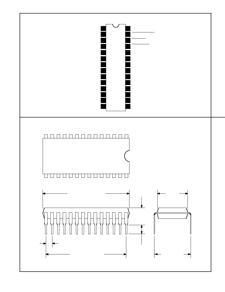
NTE1738
Integrated Circuit
TV Remote Control Receiver
Description:
The NTE1738 is a 29≠function remote≠control receiver circuit manufactured by aluminum≠gate
CMOS technology for use in television receivers, audio equipment, and the like using infrared for
transmission. It enables direct control of 12 functions at the receiver.
Features:
D
Single Power Supply
D
Wide Supply Voltage Range: 8V to 14V
D
Low Power Dissipation
D
On≠Chip Oscillator
D
Low≠Cost LC or Ceramic Oscillator used in Determining Reference Frequency (480kHz or 455kHz)
D
Information is Transmitted by Pulse Code Modulation
D
Good Noise Immunity≠Instructions are not Executed unless the Same Code is Received Three
or more Times in Succession
D
Single Transmission Frequency (40kHz or 38kHz) for Carrier Wave
D
16 TV Channels Selected Directly
D
Three Analog Functions -- Volume, Brightness and Color Saturation -- are Independently
Controlled to 64 Stages by Three 6≠Bit D/A Converters.
D
12 Instructions are Controlled at the NTE1738 Receiver, as well.
D
Has Large Tolerance in Operating Frequency between the Transmitter and the Receiver
Application:
D
Remote≠Control Receiver for TV or other Applications
Function:
The NTE1738 is designed to decode and execute instructions after three successive receptions of
the identical instruction code, providing a good noise immunity. Instructions comprise direct selection
of 16 channels, channel position high and low, color saturation high and low, normalization of volume,
brightness and color saturation, sound mute on and off, TV main power on and off, and output CALL
on and off.
In addition, 12 functional instructions can be entered from the receiver.
Absolute Maximum Ratings:
Supply Voltage (With respect to V
SS
), V
DD
≠0.3V to 15V
. . . . . . . . . . . . . . . . . . . . . . . . . . . . . . . . . . . .
Input Voltage, V
I
V
SS
V
I
V
DD
. . . . . . . . . . . . . . . . . . . . . . . . . . . . . . . . . . . . . . . . . . . . . . . . . . . . . . . . .
Output Voltage, V
O
V
SS
V
O
V
DD
. . . . . . . . . . . . . . . . . . . . . . . . . . . . . . . . . . . . . . . . . . . . . . . . . . . . . .
Maximum Power Dissipation (T
A
= +25
∞
C), P
D
300mW
. . . . . . . . . . . . . . . . . . . . . . . . . . . . . . . . . . . . .
Operating Free≠Air Temperature Range, T
opr
≠30
∞
to +70
∞
C
. . . . . . . . . . . . . . . . . . . . . . . . . . . . . . . .
Storage Temperature Range, T
stg
≠40
∞
to +126
∞
C
. . . . . . . . . . . . . . . . . . . . . . . . . . . . . . . . . . . . . . . . .
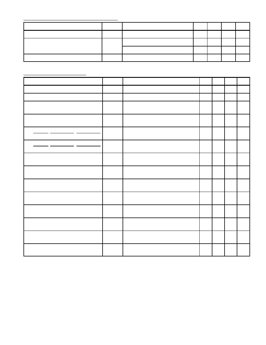
Recommended Operating Conditions:
Parameter
Symbol
Test Conditions
Min
Typ
Max
Unit
Supply Voltage
V
DD
8
12
14
V
Oscillation Frequency
f
OSC
≠
455
≠
kHz
≠
480
≠
kHz
Input Voltage, SI
V
I
5
≠
≠
V
P≠P
Electrical Characteristics: (T
A
= +25
∞
C, V
DD
= 12V unless otherwise specified)
Parameter
Symbol
Test Conditions
Min Typ Max Unit
Supply Voltage
V
DD
T
A
= ≠30
∞
to +70
∞
C, f
OSC
= 455kHz
8
12
14
V
Supply Current
I
DD
f
OSC
= 455kHz
≠
2
5
mA
Pull≠Up Resistance
I
1
to I
3
R
I
≠
20
≠
k
Low Level Output Currents
F
A to
F
D
I
OL
V
O
= 12V
5
≠
≠
mA
Low Level Output Currents
CH UP, CH DOWN, CH RESET
I
OL
V
O
= 12V
20
≠
≠
mA
Off≠State Output Currents
CH UP, CH DOWN, CH RESET
I
OZH
V
O
= 12V
≠
≠
1
µ
A
Low Level Output Currents
P
0
to P
3
I
OL
V
O
= 12V
20
≠
≠
mA
Off≠State Output Currents
P
0
to P
3
I
OZH
V
O
= 12V
≠
≠
1
µ
A
High Level Output Currents
VO, BR, CS
I
OH
V
O
= 0V
≠7
≠
≠
mA
Low Level Output Currents
VO, BR, CS
I
OL
V
O
= 12V
7
≠
≠
mA
High Level Output Currents
POWER ON/OFF, CALL MUTE
I
OH
V
O
= 0V
≠20
≠
≠
mA
Low Level Output Currents
POWER ON/OFF, CALL MUTE
I
OL
V
O
= 12V
5
≠
≠
mA
High Level Output Current
IR
I
OH
V
O
= 0V
≠15
≠
≠
mA
Low Level Output Current
IR
I
OL
V
O
= 12V
5
≠
≠
mA