NTE2564 (NPN) & NTE2565 (PNP)
Complementary Silicon Transistors
High Current Switch
Features:
D
Low Collector Emitter Saturation Voltage
D
High Current Capacity
Applications:
D
Relay Drivers
D
High Speed Inverters
D
Converters
Absolute Maximum Ratings: (T
A
= +25
∞
C unless otherwise specified)
Collector Base Voltage, V
CBO
60V
. . . . . . . . . . . . . . . . . . . . . . . . . . . . . . . . . . . . . . . . . . . . . . . . . . . . . . . .
Collector Emitter Voltage, V
CEO
30V
. . . . . . . . . . . . . . . . . . . . . . . . . . . . . . . . . . . . . . . . . . . . . . . . . . . . . .
Emitter Base Voltage, V
EBO
6V
. . . . . . . . . . . . . . . . . . . . . . . . . . . . . . . . . . . . . . . . . . . . . . . . . . . . . . . . . . .
Collector Current, I
C
Continuous
8A
. . . . . . . . . . . . . . . . . . . . . . . . . . . . . . . . . . . . . . . . . . . . . . . . . . . . . . . . . . . . . . . . . . .
Peak
15A
. . . . . . . . . . . . . . . . . . . . . . . . . . . . . . . . . . . . . . . . . . . . . . . . . . . . . . . . . . . . . . . . . . . . . . .
Collector Power Dissipation, P
C
T
A
= +25
∞
C
1.65W
. . . . . . . . . . . . . . . . . . . . . . . . . . . . . . . . . . . . . . . . . . . . . . . . . . . . . . . . . . . . . . . .
T
C
= +25
∞
C
30W
. . . . . . . . . . . . . . . . . . . . . . . . . . . . . . . . . . . . . . . . . . . . . . . . . . . . . . . . . . . . . . . . .
Operating Junction Temperature, T
J
+150
∞
C
. . . . . . . . . . . . . . . . . . . . . . . . . . . . . . . . . . . . . . . . . . . . . . .
Storage Temperature Range, T
stg
≠55
∞
to +150
∞
C
. . . . . . . . . . . . . . . . . . . . . . . . . . . . . . . . . . . . . . . . . .
Electrical Characteristics: (T
A
= +25
∞
C unless otherwise specified)
Parameter
Symbol
Test Conditions
Min
Typ
Max
Unit
Collector Cutoff Current
I
CBO
V
CB
= 40V, I
E
= 0
≠
≠
0.1
mA
Emitter Cutoff Current
I
EBO
V
EB
= 4V, I
C
= 0
≠
≠
0.1
mA
DC Current Gain
h
FE
V
CE
= 2V, I
C
= 1A
100
≠
280
V
CE
= 2V, I
C
= 4A
30
≠
≠
Gain≠Bandwidth Product
f
T
V
CE
= 5V, I
C
= 1A
≠
120
≠
MHz
Collector Emitter Saturation Volt-
age
NTE2564
V
CE(sat)
I
C
= 3A, I
B
= 150mA
≠
≠
0.4
V
NTE2565
≠
≠
0.5
V
Electrical Characteristics (Cont'd): (T
A
= +25
∞
C unless otherwise specified)
Parameter
Symbol
Test Conditions
Min
Typ
Max
Unit
Collector Base Breakdown Voltage
V
(BR)CBO
I
C
= 1mA, I
E
= 0
60
≠
≠
V
Collector Emitter Breakdown Voltage
V
(BR)CEO
I
C
= 1mA, R
BE
=
30
≠
≠
V
Emitter Base Breakdown Voltage
V
(BR)EBO
I
E
= 1mA, I
C
= 0
6
≠
≠
V
Turn≠On Time
t
on
V
CC
= 10V, V
BE
= ≠5V,
≠
0.1
≠
µ
s
Storage Time
NTE2564
t
stg
20I
B1
= ≠20I
B2
= I
C
= 4A,
Pulse Width = 20
µ
s,
Duty Cycle
1%, Note 1
≠
0.5
≠
µ
s
NTE2565
Duty Cycle
1%, Note 1
≠
0.2
≠
µ
s
Fall Time
t
f
≠
1.6
≠
µ
s
Note 1. For NTE2565, the polarity is reversed.
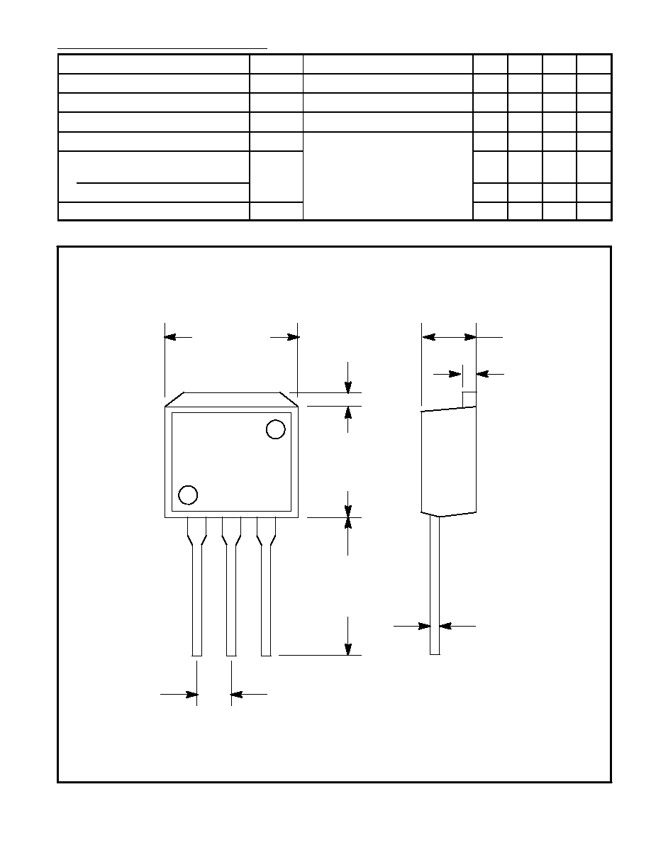
.100 (2.54)
.019 (0.5)
.177 (4.5)
.051 (1.3)
.346
(8.8)
.433
(11.0)
.035
(0.9)
.402 (10.2)
B
C
E