NTE7010
Integrated Circuit
Single Chip NTSC Color TV
Processor
w
/OSD Interface
Description:
The NTE7010 combines all the functions required for an NTSC color TV system in a 54≠Lead DIP
type package. This device includes PIF/SIF circuits, video/chroma/deflection circuits, chroma band
pass filters, red and green OSD interfaces, and 1 channel audio video switches.
PIF Circuits
D
3≠Stage Variable≠Gain PIF Amplification Stage
D
High≠Speed Response ACC with Dual Time Constants (Peak AGC)
D
Single End AFT Output with Defeat Function
D
RF Delay AGC Output (Reverse AGC)
D
Sync. Negative Detected Video Output Polarity
D
Internal Black/White Noise Inverter
SIF Circuits
D
3≠Stage Limiter Amplification Stage
D
Quadrature FM Detector Circuit with Sound Mute Function
D
1 Channel External Audio Input
D
High≠Performance Electronic Attenuator Circuit
D
Preamplifier Circuit
Video Circuit
D
2
nd
Order≠Differential≠Type Picture Sharpness Circuit (DC Control)
D
Contrast Control with Unicolor Function
D
Brightness Control with Pedestal Clamping Circuit (Variable DC Restoration Ratio)
D
External Video Input
Chroma Circuit
D
Internal
1
/
2
f
sc
Trap
D
Internal Band Pass Filter
D
ACC Circuit
D
Color Control Circuit
D
Unicolor Control Circuit
D
Color Differential Output
D
Tint Control Circuit
D
Adjustment≠Free APC Circuit
Deflection Circuits
D
High≠Performance Sync Separation Circuit
D
Adjustment≠Free Horizontal Oscillation Circuit
D
Stable Vertical Synchronization
D
Sawtooth≠Type AFC (Internal Sawtooth Wave Generator)
D
Horizontal Predrive Output
D
X≠Ray Protection Circuit
D
Vertical NFB Amplification Circuit
OSD Interface (R, G Inputs)
D
Directly Driven by
µ
≠computer
Absolute Maximum Ratings: (T
A
= +25
∞
C unless otherwise specified)
Power Supply Voltage, V
CC
13V
. . . . . . . . . . . . . . . . . . . . . . . . . . . . . . . . . . . . . . . . . . . . . . . . . . . . . . . . . .
Internal Pin Voltage, V
in
GND ≠0.3V to V
CC
+0.3V
. . . . . . . . . . . . . . . . . . . . . . . . . . . . . . . . . . . . . . . . . .
Input Signal Amplitude, e
in
4V
P≠P
. . . . . . . . . . . . . . . . . . . . . . . . . . . . . . . . . . . . . . . . . . . . . . . . . . . . . . . .
Power Dissipation, P
D
1.92W
. . . . . . . . . . . . . . . . . . . . . . . . . . . . . . . . . . . . . . . . . . . . . . . . . . . . . . . . . . . .
Derate Above 25
∞
C
15.3mW/
∞
C
. . . . . . . . . . . . . . . . . . . . . . . . . . . . . . . . . . . . . . . . . . . . . . . . . . . .
Operating Temperature Range, T
opr
≠20
∞
to +65
∞
C
. . . . . . . . . . . . . . . . . . . . . . . . . . . . . . . . . . . . . . . . .
Storage Temperature Range, T
stg
≠55
∞
to +150
∞
C
. . . . . . . . . . . . . . . . . . . . . . . . . . . . . . . . . . . . . . . . . .
Note 1. CAUTION! This device is easily damaged by high static voltage or electric fields so extreme
care should be used when handling.
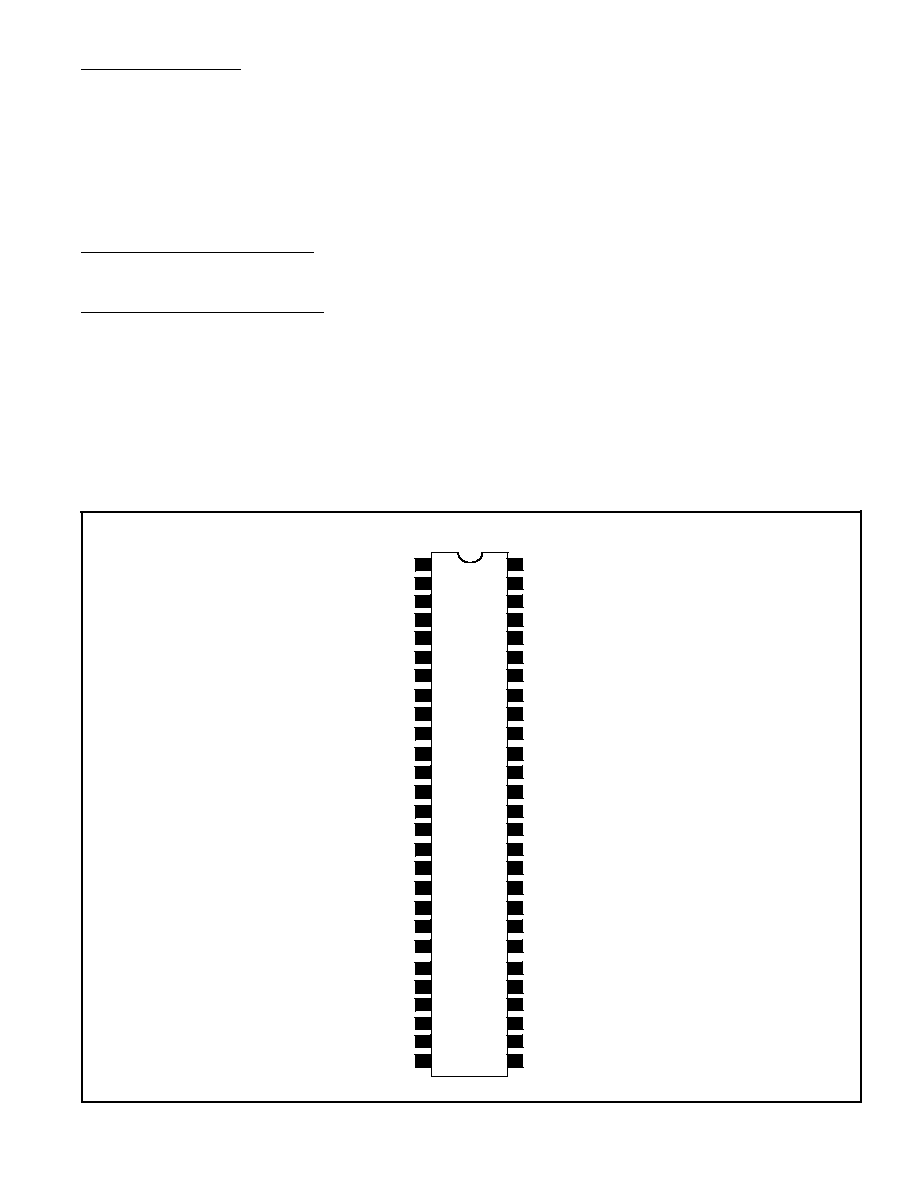
Pin Connection Diagram
PIF/SIF V
CC
H. V
CC
32f
H
VCO
V/C/D V
CC
f
c
Adjustment
2
nd
AGC
1
st
AGC
Audio TV Input
DE≠Emphasis
Chroma Input
R OSD Input
Y Output
PIF Tank (2)
SIF Input
External Audio Input
SIF Tank
TV Detection Output
Sharpness Control
Video Input
Brightness Control
Vertical Sync Sep Filter
Video Output
V/C/O GND
External Video Input
Contrast Control
Color Control
TV Input
Tint Control
PIF Tank (1)
AFT Tank
AFT Output
Audio Control
FBP Input
B≠Y Output
G≠Y Output
RF AGC Delay
PIF Input (1)
RF AGC Output
Audio Output
G OSD Input
PIF/SIF GND
1
2
3
4
5
6
7
54
53
52
51
50
49
48
8
47
9
46
PIF Input (2)
10
45
11
44
APC Filter
12
43
3.58 X'tal
R≠Y Output
13
14
15
42
41
40
16
39
17
38
18
37
19
36
20
35
21
34
Vertical NFB
Vertical Ramp
Killer Filter
SW for S≠VHS
OSD Bright Control
Horizontal AFC
Horizontal Output
X≠Ray
Vertical Output
22
23
24
25
26
27
33
32
31
30
29
28
