
NTE36 (NPN) & NTE37 (PNP)
Silicon Complementary Transistors
AF Power Amplifier, High Current Switch
Description:
The NTE36 (NPN) and NTE37 (PNP) are silicon complementary transistors in a TO3P type case de-
signed for AF power amplifier and high current switching applications.
Absolute Maximum Ratings: (T
A
= +25
∞
C unless otherwise specified)
Collector≠Emitter Voltage, V
CEO
140V
. . . . . . . . . . . . . . . . . . . . . . . . . . . . . . . . . . . . . . . . . . . . . . . . . . . . .
Collector≠Base Voltage, V
CBO
160V
. . . . . . . . . . . . . . . . . . . . . . . . . . . . . . . . . . . . . . . . . . . . . . . . . . . . . .
Emitter≠Base Voltage, V
EBO
6V
. . . . . . . . . . . . . . . . . . . . . . . . . . . . . . . . . . . . . . . . . . . . . . . . . . . . . . . . . .
Collector Current, I
C
Continuous
12A
. . . . . . . . . . . . . . . . . . . . . . . . . . . . . . . . . . . . . . . . . . . . . . . . . . . . . . . . . . . . . . . . . .
Peak
15A
. . . . . . . . . . . . . . . . . . . . . . . . . . . . . . . . . . . . . . . . . . . . . . . . . . . . . . . . . . . . . . . . . . . . . . .
Total Power Dissipation (T
C
= +25
∞
C), P
D
100W
. . . . . . . . . . . . . . . . . . . . . . . . . . . . . . . . . . . . . . . . . . .
Operating Junction Temperature, T
J
+150
∞
C
. . . . . . . . . . . . . . . . . . . . . . . . . . . . . . . . . . . . . . . . . . . . . . .
Storage Temperature Range, T
stg
≠40
∞
to +150
∞
C
. . . . . . . . . . . . . . . . . . . . . . . . . . . . . . . . . . . . . . . . . .
Electrical Characteristics: (T
A
= +25
∞
C unless otherwise specified)
Parameter
Symbol
Test Conditions
Min
Typ
Max
Unit
Collector Cutoff Current
I
CEO
V
CB
= 80V, I
E
= 0
≠
≠
0.1
mA
Emitter Cutoff Current
I
EBO
V
BE
= 4V, I
C
= 0
≠
≠
0.1
mA
DC Current Gain
h
FE1
V
CE
= 5V, I
C
= 1A
60
≠
200
h
FE2
V
CE
= 5V, I
C
= 6A
20
≠
≠
Gain Bandwidth Product
f
T
V
CE
= 5V, I
C
= 1A
≠
15
≠
MHz
Output Capacitance
NTE36
NTE37
C
ob
V
CB
= 10V, f = 1MHz
≠
≠
210
300
≠
≠
pF
Base≠Emitter Voltage
V
BE
V
CE
= 5V, I
C
= 1A
≠
≠
1.5
V
Collector≠Emitter Saturation Voltage
NTE36
NTE37
V
CE(sat)
I
C
= 5A, I
B
= 500mA
≠
≠
0.6
1.1
2.5
≠
V
Electrical Characteristics (Cont'd): (T
A
= +25
∞
C unless otherwise specified)
Parameter
Symbol
Test Conditions
Min
Typ
Max
Unit
Collector≠Base Breakdown Voltage
V
(BR)CBO
I
C
= 5mA, I
E
= 0
160
≠
≠
V
Collector≠Emitter Breakdown Voltage
V
(BR)CEO
I
C
= 5mA, R
BE
=
140
≠
≠
V
I
C
= 50mA, R
BE
=
140
≠
≠
V
Emitter≠Base Breakdown Voltage
V
(BR)EBO
I
E
= 5mA, I
C
= 0
6
≠
≠
V
Turn≠On Time
NTE36
NTE37
t
on
10I
B1
= ≠10I
B2
= I
C
= 1A,
PW = 20
µ
s
≠
≠
0.26
0.25
≠
≠
µ
s
Fall Time
NTE36
NTE37
t
f
≠
≠
0.68
0.53
≠
≠
µ
s
Storage Time
NTE36
NTE37
t
on
≠
≠
6.88
1.61
≠
≠
µ
s
Note 1. Matched complementary pairs are available upon request (NTE37MCP). Matched comple-
mentary pairs have their gain specification (h
FE
) matched to within 10% of each other.
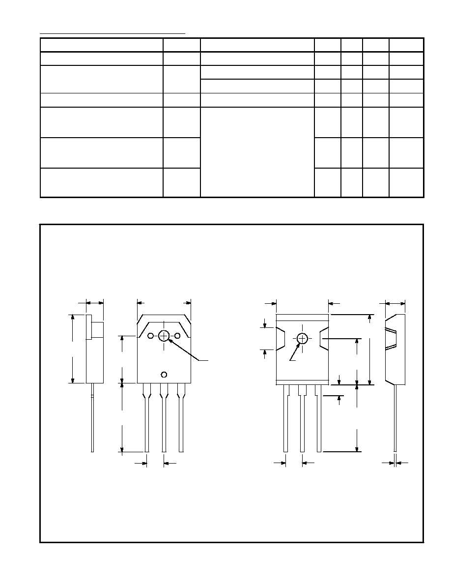
.787
(20.0)
OR
(Note)
NOTE: Either case style may be shipped depending on stock.
.126
(3.22)
Dia
B
C
E
.130 (3.3)
Dia
.215 (5.47)
.025 (0.65)
.197 (5.0)
.670 (17.0)
Max
.177 (4.5)
.217
(5.5)
.747
(19.0)
Min
.590
(15.0)
.866
(22.0)
.615 (15.62)
.591
(15.02)
.787
(20.0)
.215 (5.47)
B
C
E
.190 (4.82)