
NTE7060
Integrated Circuit
NTSC Single Chip Color TV Signal Processor
Description:
The NTE7060 is an integrated circuit in a 52≠Lead DIP type package that combines all of the signal
(VIF, SIF, Video, Color and Synchronous Signal) processing circuits in NTSC color TV onto one chip.
Features:
D
VIF Circuit using PLL Complete Synchronous Detection
D
Audio External Input Pin and Volume Adjusting Circuit Built≠In
D
Y Delay Line Built≠In and Y Delay Line Switchable
D
Block Level Compensation Circuit Built≠In
D
3.58MHz BPF Built≠In
D
APC Killer Filter Built≠In (No Adjustment of ACP)
D
On≠Screen Pin Attached (Only for Green and Other Output Blanking)
D
Compatible with S≠VHS System (3.58MHz ON/OFF Switching)
D
No Adjustment of Horizontal/Vertical Oscillation Frequency
D
Horizontal Synchronous Lock Detecting Pin Attached
D
Service Switch Circuit Built≠In (Vertical Out Stop, Y Out Blanking)
D
Y Output is Black Level when No Synchronous Signal is Input
Absolute Maximum Ratings: (T
A
= +25
∞
C unless otherwise specified)
Supply Voltage, V
CC1
12V
. . . . . . . . . . . . . . . . . . . . . . . . . . . . . . . . . . . . . . . . . . . . . . . . . . . . . . . . . . . . . . .
Supply Current (I
43
)
, I
CC
82mA
. . . . . . . . . . . . . . . . . . . . . . . . . . . . . . . . . . . . . . . . . . . . . . . . . . . . . . . . . . .
Supply Current (I
9
)
, I
CC
30mA
. . . . . . . . . . . . . . . . . . . . . . . . . . . . . . . . . . . . . . . . . . . . . . . . . . . . . . . . . . .
Supply Current (I
32≠19
)
, I
CC
61mA
. . . . . . . . . . . . . . . . . . . . . . . . . . . . . . . . . . . . . . . . . . . . . . . . . . . . . . . .
Power Dissipation (T
A
= +70
∞
C), P
D
1.3mW
. . . . . . . . . . . . . . . . . . . . . . . . . . . . . . . . . . . . . . . . . . . . . . .
Operating Ambient Temperature Range, T
opr
≠20
∞
to +70
∞
C
. . . . . . . . . . . . . . . . . . . . . . . . . . . . . . . . . .
Storage Temperature Range, T
stg
≠55
∞
to +150
∞
C
. . . . . . . . . . . . . . . . . . . . . . . . . . . . . . . . . . . . . . . . . .
Recommended Operating Range: (T
A
= +25
∞
C unless otherwise specified)
Operating Supply Voltage Range, V
CC1
8.1V to 9.9V
. . . . . . . . . . . . . . . . . . . . . . . . . . . . . . . . . . . . . . .
Operating Supply Voltage Range, V
CC3,4
4.5V to 5.5V
. . . . . . . . . . . . . . . . . . . . . . . . . . . . . . . . . . . . . .
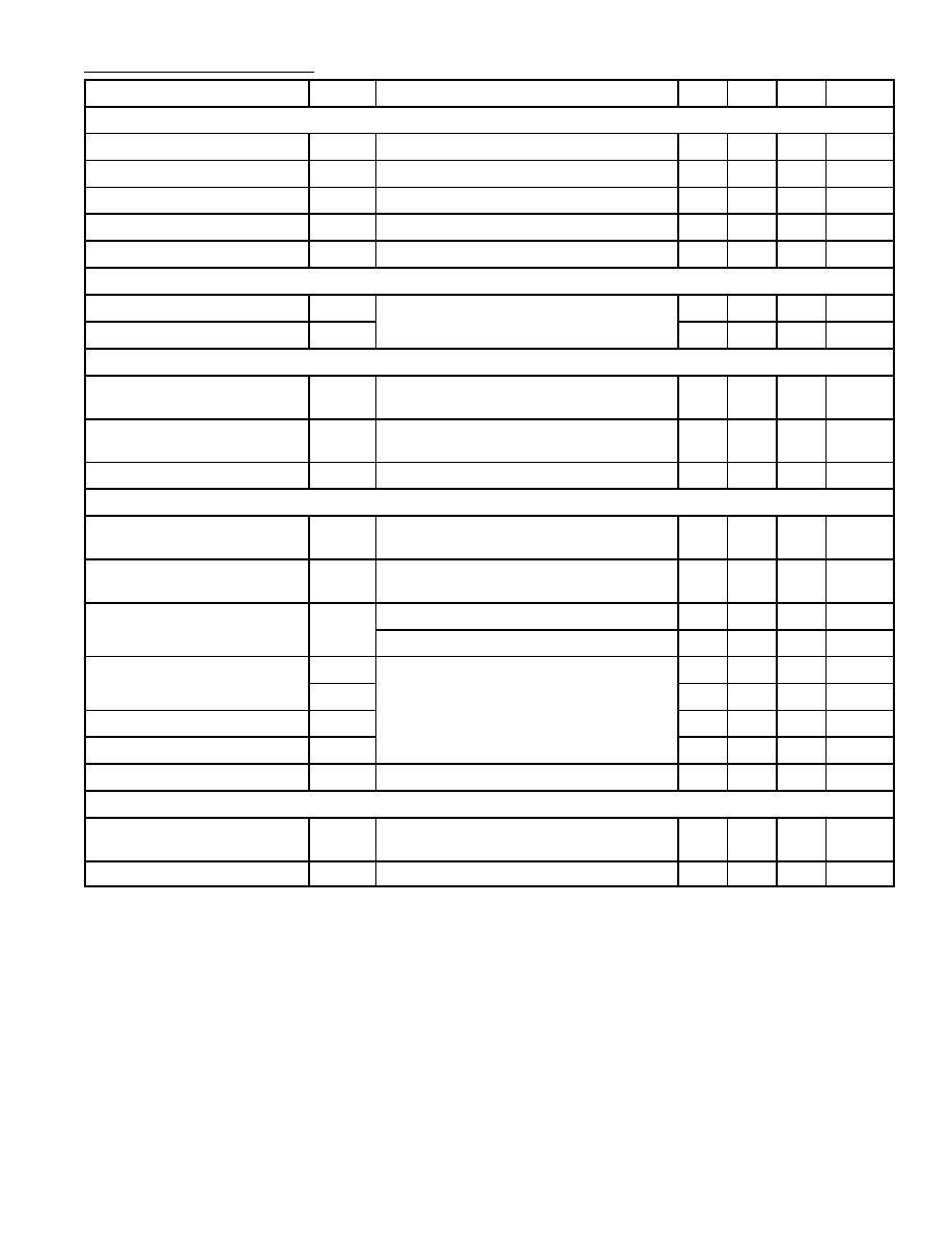
Electrical Characteristics: (T
A
= +25
∞
C unless otherwise specified)
Parameter
Symbol
Test Conditions
Min
Typ
Max
Unit
VIF Section
Video Detection Output
V
O21
M = 87.5%, V
in
= 80dB
µ
1.75
2.0
2.25
V
P≠P
Video Frequency Characteristics
f
C
≠3dB Frequency for 1MHz Detection Output
4.0
5.5
≠
MHz
VCO Oscillator Sensitivity
b
V
20
= 0.2V (DC: About 2V)
3.0
4.3
6.5
kHz/mV
RF AGC Sensitivity
G
RF
Difference in Input Level of V
33
= 1V
7V
≠
1.5
3.0
dB
AFC Phase Detector Sensitivity
µ
AFC
R
L
= 100k
//100k
25
40
55
mV/kHz
SIF Section
Audio Detection Output
V
O27
f
O
= 4.5MHz, V
in
= 100dB
µ
,
±
125
155
185
mV
rms
Audio Output
V
O28
f =
±
25kHz, f
m
= 1kHz
410
530
650
mV
rms
Video Signal Processing Section
Video Voltage Gain
A
V
Input: f = 1MHz, 0.2V
P≠P
,
Contrast VR: Max
7.6
9.3
12.2
Times
Video Frequency Characteristics
f
YC
Picture Quality VR: Min.,
3dB Down from f = 1MHz
4.5
5.5
≠
MHz
Brightness Oscillator Sensitivity
BR
Bright VR = 7.5V to 8V
≠4.5
≠3.6
≠2.7
Times
Chroma Signal Processing Section
Color Difference Output (Typ.)
e
O1B
B≠Y Color Bar Signal
Color VR: 3.3V, Contrast VR: 5V
2.3
3.0
3.7
V
P≠P
Color Difference Output (Max.)
e
O2B
B≠Y Color Bar Signal
Color VR: 5V, Contrast VR: 5V
3.7
4.7
5.7
V
P≠P
ACC Characteristics
ACC
Burst 200
400mV
P≠P
0.9
1.0
1.1
Times
Burst 200
20mV
P≠P
0.5
0.7
1.0
Times
Demodulator Output Ratio
R/B
Color Bar Signal (Burst 200mV
P≠P
)
0.72
0.96
1.2
Times
G/B
0.22
0.31
0.39
Times
Demodulator Angle R
R
89
104
119
Deg.
Demodulator Angle G
G
225
240
255
Deg.
Color Killer Tolerance
e
K
Color Bar Signal Burst 200mV
P≠P
= 0dB
≠55
≠42
≠30
dB
Synchronous Signal Processing Section
Horizontal Natural Oscillation
Frequency
f
HO
Output frequency of Pin4
15.45 15.75 16.05
kHz
Horizontal Pull≠In Range
f
PH
15.25
≠
16.25
kHz

V
CC1
(9V)
V
CC3
(5V)
V
CC4
(5V)
V
CC2
(6.1V)
Pin Connection Diagram
1.813 (46.05) Max
.600 (15.24)
.512 (13.0)
.070 (1.77)
.217
(5.5)
Max
.118
(3.0)
Min
1.750 (44.5)
1
26
52
27
SIF Coil
Vertical Sync Output
Sync Separator Input
R≠Y Output
Audio Feedback
SIF Input/Volume Adjustment
Horizontal AFC Output
GND
Brightness Adjustment
On≠Screen Input (G≠Y)
ACC Detection Filter
Vertical Sync Input
B≠Y Output
G≠Y Output
1
2
3
4
GND
Vertical Output
X≠Ray Protect
Horizontal Output
5
6
Horizontal Oscillation (VCO)
7
8
FBP Sawtooth Input
52
51
50
49
Sharpness
Pedestal Blank
Black Level Compensartion
48
Y Output
47
46
45
9
44
Tint Adjustment
10
Flyback Pulse Input
11
43
42
Color Saturation Adjustment
12
41
Contrast Adjustment/Service SW
13
Y Input
40
3.58MHz Oscillation
14
39
15
Chroma Input
38
VIF Input
AFC Output
AFC Tank Circuit
RF AGC Output
16
Horizontal AFC Lock Detect
17
VCO Coil Pin
18
VCO Coil Pin
19
20
APC Filter
37
GND
36
VIF Input
35
34
33
IF AGC Output/AV Switching
21
Video Detection Output
32
RF AGC Delay Adjustment
22
AFC Tank Circuit
23
31
30
SIF Coil
24
29
Audio Output
25
28
Audio Detection Output/External Audio Input
26
27