
NTE56004 thru NTE56010
TRIAC, 15 Amp
The NTE56004 thru NTE56010 series of TRIACs are designed primarily for fullÙwave AC control ap-
plications, such as solidÙstate relays, motor controls, heating controls and power supplies; or wherev-
er fullÙwave silicon gate controlled solidÙstate devices are needed. TRIAC type thyristors switch from
a blocking to a conducting state for either polarity of applied anode voltage with positive or negative
gate triggering.
Features:
D
Blocking Voltage from 200 to 800 Volts
D
All Diffused and Glass Passivated Junctions
D
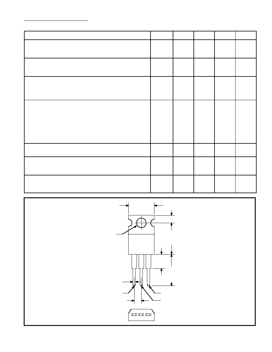
Small, Rugged, TO220 package for Low Thermal Resistance, High Heat Dissipation and Durability
D
Gate Triggering specified in Four Quadrants
Absolute Maximum Ratings:
Peak Repetitive OffÙState Voltage, (T
J
= Ù40
¯
to 125
¯
C), V
DRM
NTE56004
200V
. . . . . . . . . . . . . . . . . . . . . . . . . . . . . . . . . . . . . . . . . . . . . . . . . . . . . . . . . . . . . . . .
NTE56006
400V
. . . . . . . . . . . . . . . . . . . . . . . . . . . . . . . . . . . . . . . . . . . . . . . . . . . . . . . . . . . . . . . .
NTE56008
600V
. . . . . . . . . . . . . . . . . . . . . . . . . . . . . . . . . . . . . . . . . . . . . . . . . . . . . . . . . . . . . . . .
NTE56010
800V
. . . . . . . . . . . . . . . . . . . . . . . . . . . . . . . . . . . . . . . . . . . . . . . . . . . . . . . . . . . . . . . .
Peak Gate Voltage, V
GM
10V
. . . . . . . . . . . . . . . . . . . . . . . . . . . . . . . . . . . . . . . . . . . . . . . . . . . . . . . . . . .
OnÙState Current RMS (Full Cycle Sine Wave 50 to 60Hz,T
C
= +90
¯
C), I
T(RMS)
15A
. . . . . . . . . . .
Circuit Fusing (t = 8.3ms) I
2
t
93A
2
s
. . . . . . . . . . . . . . . . . . . . . . . . . . . . . . . . . . . . . . . . . . . . . . . . . . . . . .
Peak Surge Current (One Full Cycle, 60Hz, T
C
= +80
¯
C), I
TSM
Preceded and followed by rated current
150A
. . . . . . . . . . . . . . . . . . . . . . . . . . . . . . . . . . . . . . .
Peak Gate Power (T
C
= +80
¯
C, Pulse Width = 2
ç
s), P
GM
20W
. . . . . . . . . . . . . . . . . . . . . . . . . . . . . .
Average Gate Power (T
C
= +80
¯
C, t = 8.3ms), P
G(AV)
500mW
. . . . . . . . . . . . . . . . . . . . . . . . . . . . . .
Peak Gate Current, I
GM
2A
. . . . . . . . . . . . . . . . . . . . . . . . . . . . . . . . . . . . . . . . . . . . . . . . . . . . . . . . . . . . .
Operating Junction Temperature Range, T
J
Ù40
¯
to +125
¯
C
. . . . . . . . . . . . . . . . . . . . . . . . . . . . . . . . .
Storage Temperature Range, T
stg
Ù40
¯
to +150
¯
C
. . . . . . . . . . . . . . . . . . . . . . . . . . . . . . . . . . . . . . . . .
Thermal Resistance, JunctionÙtoÙCase, R
thJC
2
¯
C/W
. . . . . . . . . . . . . . . . . . . . . . . . . . . . . . . . . . . . .
Electrical Characteristics (T
C
= 25
¯
C, and either polarity of MT2 to MT1 Voltage, unless
otherwise noted)
Characteristics
Symbol
Min
Typ
Max
Unit
Peak Forward or Reverse Blocking Current
(Rated V
DRM
, or V
RRM
, Gate open)
T
J
=25
¯
C
T
J
=125
¯
C
I
DRM
,
I
RRM
Ù
Ù
Ù
Ù
10
2
ç
A
mA
Peak OnÙState Voltage
(I
TM
= 21 A Peak; Pulse Width = 1 to 2ms,
Duty Cycle
2%)
V
TM
Ù
1.3
1.6
Volts
Gate Trigger Current (Continuous dc)
(V
D
= 12Vdc, R
L
= 100 Ohms)
MT2(+) G(+), MT2(+) G(Ù), MT2(Ù) G(Ù)
MT2(Ù), G(+)
I
GT
Ù
Ù
Ù
Ù
50
75
mA
Gate Trigger Voltage (Continuous dc)
(V
D
= 12Vdc, R
L
= 100 Ohms)
MT2(+) G(+), MT2(+) G(Ù)
MT2(Ù) G(Ù)
MT2(Ù) G(+)
(V
D
= Rated V
DRM
, R
L
= 10k Ohms, T
J
= 110
¯
C)
MT2(+) G(+), MT2(Ù) G(Ù), MT2(+) G(Ù)
MT2(Ù) G(+)
V
GT
Ù
Ù
Ù
0.2
0.2
0.9
1.1
1.4
Ù
Ù
2
2
2.5
Ù
Ù
Volts
Holding Current (Either Direction)
(V
D
= 12Vdc, I
T
= 200mA, Gate Open)
I
H
Ù
6
40
mA
TurnÙOn Time
(V
D
= Rated V
DRM
, I
TM
= 17A)
(I
GT
= 120mA, Rise Time = 0.1
ç
s, Pulse Width = 2
ç
s)
t
gt
Ù
1.5
Ù
ç
s
Critical Rate of Rise of Commutation Voltage
(V
D
= Rated V
DRM
, I
TM
= 21 A, Commutating
di/dt = 8A/ms, Gate Unenergized, T
C
= 80
¯
C)
dv/dt(c)
Ù
5
Ù
V/
ç
s
.250
(6.35)
Max
.500
(12.7)
Max
.500
(12.7)
Min
.110 (2.79)
.420 (10.67)
Max
.070 (1.78) Max
MT
1
.100 (2.54)
MT
2
Gate
.147 (3.75)
Dia Max
MT
2